DSP-10 Project
March 2014: Updated, Improved 24-bit tuning, v3.96 of Software!
November 2016: Again Updated, Information on running under Puppy Linux
The DSP-10 is an amateur-radio, software-defined 2-meter transceiver that can be built at home. It operates not only on SSB, FM and CW, but also on three Weak-Signal modes. Features are tailored to operation on VHF, UHF and Microwave frequencies.
A three-part article by Bob Larkin, W7PUA, published in QST magazine for September, October and November of 1999 describes the project. Copies of the article can be downloaded from the ARRL Web site. The transceiver hardware consists of a single PC board for the RF parts and an Analog Devices EZ-Kit Lite demo board for the I-F and audio processing. This is all controlled by any PC through a serial port. All programs are available as 'Free Software.'
A note on availability. As time goes by, some of the parts used in this project have been discontinued, or put on special order, by their manufacturers. Probably the best way for new builders to get the parts is to post a note to the "E-mail Reflector," listed below, asking if someone has a kit of parts they would like to sell. Several hundred of these kits were sold, and some are not yet built. They may not include parts like the box, so ask about what is being offered.
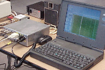
On the right is W7LHL's DSP-10 setup. He uses a laptop to control the transceiver. All DSP-10 hardware is inside the die-cast aluminum box. As shown here, Ernie was using a 1296 MHz transverter to receive the NU7Z beacon.
The transceiver is very useful on 2-meters as a standard radio and has a number of interesting features. But, this was not the motivating force behind the project. There is a great potential for weak-signal QSO's if the proper processing is used. The DSP-10 software is a start towards achieving this goal. It makes a number of tools available to the experimenter interested in this area. An article discussing these potentials was published for the 10th EME Conference, held in Prague in 2002.
The transceiver is low power, about 20 milliwatts, but there is provision for adding an 8-Watt amplifier (see below). However, the low power can be ideal for use with transverters, since most of these use attenuators to throw away the higher power anyway.
Run under Puppy Linux
![]() The combination of Linux and the DOSBox program have allowed the DSP-10
to be run on newer PC's. The timing issues that are present when this
is tried under MS-Windows are solved by using Linux. This also
allows the use of a USB port to RS-232 adapter to replace the older COM
ports. The Linux distribution that is currently being used is "Puppy 5.2.8
Linux." The has the advantage of being small enough to run from memory
emulation of a hard drive and not require either a full installation nor
drive partitioning.
The combination of Linux and the DOSBox program have allowed the DSP-10
to be run on newer PC's. The timing issues that are present when this
is tried under MS-Windows are solved by using Linux. This also
allows the use of a USB port to RS-232 adapter to replace the older COM
ports. The Linux distribution that is currently being used is "Puppy 5.2.8
Linux." The has the advantage of being small enough to run from memory
emulation of a hard drive and not require either a full installation nor
drive partitioning.
The .ISO file for creating a CD, or USB stick, with both Puppy and the DOSBox DSP-10 are at the (Revised Nov 2016, thanks to KF7OVD and KD7TS for making this available) Puppy/DSP-10 download. The MD5SUM for this file is 4aedd65e1abe5aaeae47c9173849012f puppy-5.2.8_dsp10_5.iso
A text file has information on installing and running under Puppy. UPDATE 2025: The UEFI complexities have made running the Puppy ISO file more difficult. Various laptops work, but the newer ones may need special care. Try a "UEFI Puppy Linux" search to help figure out your PC.
Screen shots of the DSP-10 running under Puppy are available as single sized DSP-10 window as well as Puppy with a double sized DSP-10 window.
Version 3.96 Software
![]() This latest version of the control software is available. Details
and download information is
available below.
This latest version of the control software is available. Details
and download information is
available below.
RS-232 GPS Switch
Box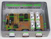
If you want to have the fully automatic time setting, this add-on is the solution. Johan, KC7WW and Jimmy, W7CQ, have collaborated to design an RS-232 Switch. This little box goes into the serial line between the DSP-10 hardware and the PC. A separate 9-pin connector then goes to the GPS to allow the radio to set precise time and to determine the station location. Up to two additional connectors can be added for future expansion. Revision 3.80 (or later) software is setup to control the switch box through the serial link.
Complete information on the switch box is available for download from Jimmy's web site. No PC boards are being offered, but the design files are ready-to-go.
DSP-10 User's Manual
The User's Manual
is quite up-to-date, has many improved sections and added reference
material. KD7TS has spent a huge amount of time on this and taken
the wild collection of notes and emails and turned them into a
carefully linked book arranged in good order. This manual is not
only instructions for operating the radio, but study of the material
will give insights to how it all works. Details such as the
configuration file setup are now covered in detail. The manual is
available on-line
from Mike's web site. Check this out; it is a
fine aid for the project!
DSP-10 Command Summary
![]() Jimmy, W7CQ has carefully checked the Command
Summary. It fits neatly on two letter-size pages and makes a great way
to find the commands you can't remember! Fully up-to-date for Version
3.96, it is
available for download from Jimmy's web site as a PDF
file and suitable for printing.
Jimmy, W7CQ has carefully checked the Command
Summary. It fits neatly on two letter-size pages and makes a great way
to find the commands you can't remember! Fully up-to-date for Version
3.96, it is
available for download from Jimmy's web site as a PDF
file and suitable for printing.
DSP-10 Features
If you are new to the DSP-10 transceiver, you should look at the original magazine articles, and at the User's Manual. But, if you want the quick tour, here is a summary:
In addition there are three weak-signal modes fully integrated between the hardware and software, as follows:
EME-2 Mode
- Automated transmit/receive timing and Doppler correction for
self-echoes on EME. Two trace spectral display provides any
amount of power integration of signal and noise powers allowing
echoes to be seen 30 dB below the audible levels.
PUA-43 Mode uses forty-three tone FSK with adaptable "very long-term integration." This mode provides automated transmit and receive for communication by terrestrial or EME paths, allowing an extreme ability to trade-off of data rate against signal strength. "Message Estimation" is used to always show the most-likely message along with a second alternative. The character color is indicative of the confidence level for each symbol.
No low-signal threshold effects occur
with PUA43; there are no fundamental limits to the sensitivity
available. The mode trades off sensitivity for speed as desired.
To the right is
a sample of EME reception of the PUA43 mode. Note that no signal
is visible on the spectral waterfall, yet copy is 100%. Click on
the photo to make it full-sized.
LTI Mode - This stands for Long-Term Integration (the same as averaging). Although called a "mode" in the operation of the DSP-10, this is really a measurement tool. Transmission is essentially the same as CW. Reception uses the same weak-signal noise averaging as EME-2 and PUA43 to extract spectral traces on extremely-weak signals, limited only by one's patience! Overnight tests show -185 dBm signals with well defined traces (that's a little over 0.0001 microvolts!). The display allows one to actually measure these signal levels to within a dB or two. This has been a useful and fun tool for exploring propagation paths. Like the other modes, it can be operated with EME Doppler corrections.
DSP-10 Hardware requirements: Full utilization of these weak signal modes requires a frequency stability of about 1 Hz at the operating frequency (it may not be 2-meters because of external transverters). The programs work with any PC with DOS, a serial port and VGA graphics. No math coprocessor is required, but it speeds some operations quite a bit. These modes require the RF hardware of the DSP-10. Some limited receiving functions are available with the Audio Processor option described below.
Examples of Weak-Signal Mode Operation
What can be done with the DSP-10 using these programs? Basically these are a set of tools that are being made available to anyone that wants to do serious weak-signal experiments. The package allows QSO's with stations that are much too weak for conventional modes. This opens many interesting possibilities for contacts. Here is a sampling of some early work:
E-Mail Reflector for the DSP-10
Thanks to Jimmy, W7CQ and Al, K3TKJ, we have an email reflector to distribute information on the DSP-10 transceiver project. The reflector is on mailman.qth.net and will cover all aspects of this project. You can send an email to the reflector, after you are a subscriber. This will then be sent to all of the other subscribers. This will give a way for all those interested in the project to share their questions, answers and experiences, quickly and informally.
To subscribe, unsubscribe, or to read the archives, go to the qth.net Web Site.
8-Watt "Brickette" Amplifier
This 2-meter amplifier, specifically for the DSP-10, raises the transmit power. Full details are in the June 2000 QST magazine article. Finished PC boards are no longer available. Files for making boards are available in ExpressPCB format thanks to KD7TS, and also in Gerber format. Those wanting to purchase prototype quantities of boards (check the email reflector, first---someone may have some) can use these files, or you can use them to alter the design! This was the amplifier used by W7PUA for the 5-Watt EME-2 self-echo test mentioned above. No part kits are available.
Hardware Information
Be sure to check Part Buying Information. for updates.
PC BOARDS: Many hundreds of the PC Boards were sold as kits in the 2000 to 2004 time frame. These are no longer available, and neither are the plain PCB's. As mentioned above, check on the email reflector for strays.
PCB Gerber Files For those that want to make a PCB, these Gerber Files are the complete information. If you are not familiar with the use of Gerber files, this may not be for you! I cannot support this, beyond making the files available, and there are no guarantees! Also, be sure that you are going to be able to acquire all the needed parts before proceeding with a bare board. Gerber files have been a common file format for PCB makers for years. Rumors have it that AP Circuitscan do prototypes from Gerber files. (13MarNov08)
Assembly Notes, Rev 4.5, are available for the hardware. Revision information at the bottom of the Assembly Notes indicates all changes. Note: Rev 4.5 has new board assembly information.
Steve Bible, N7HPR, has written an excellent Assembly Manual that should be of great help with the board assembly.
AUTOMATIC REFERENCE OSCILLATOR SWITCHING from WW2R. Dave has designed a neat circuit to allow the signal from an external 10 MHz reference oscillator to disable an internal oscillator (off the DSP-10 board), and connect in the external reference. Full construction details are available on the WW2R Web site.
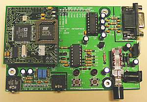 DSPx+KDSP10 and the EZKit -
The cost of the EZKit Lite has become a problem since the DSP-10 project
was first published. Fortunately, Lyle Johnson, KK7P, in cooperation
with TAPR has produced a fine substitute. As shown on the left, it
consists of a commercially assembled,
very small, 2185 DSP board, with flash memory and a good CODEC, called
the DSPx. This board plugs into an interface board, the KDSP10,
that comes as a kit. The total assembly
replaces the functions of the EZKit and provides higher performance in
most areas. NOTE-As of May 2013, the availability of DSPx and KDSP10
boards is uncertain.
DSPx+KDSP10 and the EZKit -
The cost of the EZKit Lite has become a problem since the DSP-10 project
was first published. Fortunately, Lyle Johnson, KK7P, in cooperation
with TAPR has produced a fine substitute. As shown on the left, it
consists of a commercially assembled,
very small, 2185 DSP board, with flash memory and a good CODEC, called
the DSPx. This board plugs into an interface board, the KDSP10,
that comes as a kit. The total assembly
replaces the functions of the EZKit and provides higher performance in
most areas. NOTE-As of May 2013, the availability of DSPx and KDSP10
boards is uncertain.
Present plans are to require the DSPx for future DSP software, as the EZKit has about run out of "real time." The 2+ increase in capability of the DSPx solves this problem and has improved CODEC performance, as a bonus (Nov 2005). Update 2013: This has moved slowly, but is still active. The software for the DSP has now been separated for the EZ-Kit Lite and the DSPx. Information is under UHF3 below. Future updates for the DSPx (only) will be available by the end of 2013--at least that is the plan.
EZ-Kit Users should note that
probably the last update for the EZKit is the current version 35.
This includes the
abiity to tune in 0.0014 Hz steps. I will try to fix any major bugs for
the EZ-Kit, but no additions or revisions are expected.
![]() PC Program -
Version 3.96, the latest PC program UHFA.EXE for the PC, is
available for download. It serves
as the front panel and
control for the DSP-10 radio. Be sure that the DSP program, UHF3 or
UHF3X is version 30 (previously called 3.0) or later and if sub-Hz
tuning is desired, you should update to UHF3 version 35. Also check
the READ396.TXT file inside the ZIP for more info.
PC Program -
Version 3.96, the latest PC program UHFA.EXE for the PC, is
available for download. It serves
as the front panel and
control for the DSP-10 radio. Be sure that the DSP program, UHF3 or
UHF3X is version 30 (previously called 3.0) or later and if sub-Hz
tuning is desired, you should update to UHF3 version 35. Also check
the READ396.TXT file inside the ZIP for more info.
Added July 2025 (RSL): Source code for v3.96..
![]() DSP Program - The set of three programs in
uhf3_35a.zip
provide all that is needed for the DSP. It includes the following
programs
DSP Program - The set of three programs in
uhf3_35a.zip
provide all that is needed for the DSP. It includes the following
programs
Notes are included in the ZIP file above. For each
DSP-10, only one of the three programs would be used at a time.
![]() DSPx Flash Bank 1: All updates to the DSP program
for the DSPx (not EZKit) are done by loading an Intel hex file to Bank
1. This happens by running a single DOS BAT file. The details of this
are on a separate page.
DSPx Flash Bank 1: All updates to the DSP program
for the DSPx (not EZKit) are done by loading an Intel hex file to Bank
1. This happens by running a single DOS BAT file. The details of this
are on a separate page.
Note that there appears to be no advantage to loading the DSP program, of the form UHF3Xzzz.EXE, into the DSPx processor on a temporary basis. This can be done, as the Monitor for the DSPx supports such. However, it is essentially as easy to place the program the .HEX file into flash memory Bank 1. From then on, the DSP for the DSP-10 will come up running at power turn on. Only the .HEX form of DSPx programs are being distributed.
![]() DSPx Flash Bank 0: Users of the DSPx hardware normally only make
changes to Flash Bank 1 as just above. The Monitor that loads programs
and other very basic operations is located in Flash Bank 0.
More information on changing or copying this Bank is available at
KD7TS' Flash Bank 0 web page.
DSPx Flash Bank 0: Users of the DSPx hardware normally only make
changes to Flash Bank 1 as just above. The Monitor that loads programs
and other very basic operations is located in Flash Bank 0.
More information on changing or copying this Bank is available at
KD7TS' Flash Bank 0 web page.
EZFAST Shareware: For loading the EZ-Kit with the DSP program, you can use the Windows loader provided by Analog Devices. Much faster is Dwight Elvey's shareware EZFAST.COM, but you must have the current Ver 1.03. It is available for download. Be sure to study the EZFAST.DOC readme file that is with it (it is a pure text document, not Word).
Ver 3.50 PC Source Code and Ver 3.2 DSP Source Code: You can download the 'Free Software' for the PC software (Borland ver 4.0 or 4.5) (217K zipped) and the DSP software source. This second item is written in Analog Devices assembly language and can be assembled into UHF3.EXE, Rev 3.2 with the tools supplied with the EZ-Kit. This allows changes and additions to the DSP software, and is NOT required to just operate the DSP-10. Revision 3.96 Source code is in the works.
SENDDOLR DSP-10 to Monitor: This is an PC DOS program to support loading of a new version of UHF3.EXE on top of an EPROM version of UHF3.EXE. Details are in a RD_SD18.TXT text file that is zipped with the executable. In the past, this program has had problems, associated with capturing the DSP-10 process. A new version 1.8 of SENDDOLR is available. This is now called SNDDLR18.EXE and is inside SNDDLR18.ZIP. This should reliably catch the DSP-10 process.(28May2013)
EZFAST Shareware: For loading the EZ-Kit with the DSP program, you can use the Windows loader provided by Analog Devices. Much faster is Dwight Elvey's shareware EZFAST.COM, but you must have the current Ver 1.03. It is available for download. Be sure to study the EZFAST.DOC readme file that is with it (it is a pure text document, not Word).
DSP-10 DSP Interface To assist those "talking" with the DSP unit, there is now a summary of the interface. This has all the commands and the status definitions and is here for download.
PUA43 SPEC To define the PUA43 mode, there is aspecification available for download.
Information for Builders
Assembly Manual - Steve Bible, N7HPR, has written an excellent Assembly Manual that should be of great help with the board assembly. Many thanks to Steve for all his efforts.
Corrections:
1 - The connections on the EZ-Kit to P3, Pin 31 and P3, Pin 32 are
backwards. A corrected portion of QST Fig 11
shows the change. It also reflects on
QST Fig 10, but no wiring is changed.
(16 Nov 99)
2 - R49 in the schematic and the part information should be 47K
(not 1.8K.) (16 Nov 99)
3 - R21 should be 10K (not 100K); this causes the gain to be 20
dB too high. (1 Dec 99)
4 - R108 should be 4.7K Ohms (not 470). Some combinations of U107
and U104 have been found to have the data line at U104 switching
too early. These are cascaded shift registers and the timing is
quite close. The R108 resistor change slows down the data line
going to U104, making the timing less critical. (1 Dec 99)
5 - C71 must be NPO temperature stable type. See Parts
Information. (5 Nov 00)
Improvements:
1 - R16 can be changed from 10K to 6.8K. This centers the output
Voltage on U10A better. I am unaware that the old value had
actually caused any clipping on U10A output, though. (1 Dec 99)
2 - U15 Mixer Grounding can cause major degradation in
sensitivity. It is very important that this is dealt with!
All the information is on U15 modification
page. The modification is simple but the improvement
can be big. (21 Dec 01)
Important! - The silk-screen legend is backwards for the 78L05 regulators, U13 and U103. The flat sides of both TO-92 packages should be towards the top of the board. There is no problem in installing the parts, of course. The sketch of the package included with the board is correct. Thanks to KD7TS for catching this. (Added 26 Oct 99)
Note 8 of the Assembly Notes says that all chip caps can be 1206 size. This is NOT true for the 0.01 uF and 470 pF values. These should be 0805 size. Also the 0.01 uF part number in the 4.1 addendum to the Assembly Notes is for the larger size. See the Part Information page for more information and supplier part numbers.
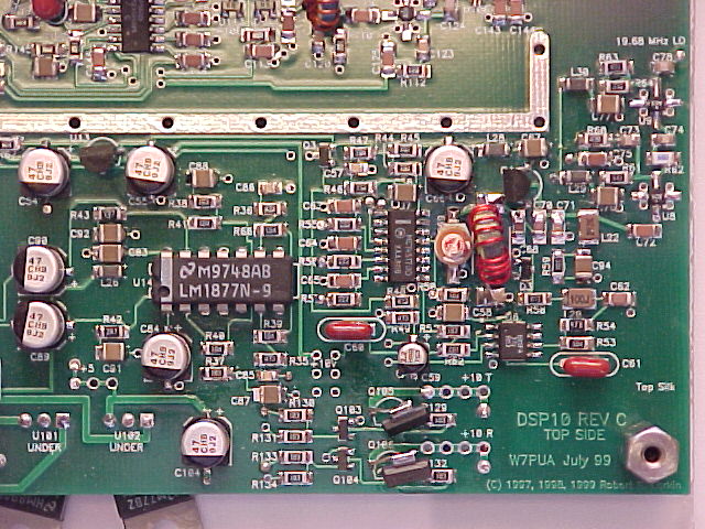
"SR105" Diode - When the DSP program is first started and before the PC program is run, the DSP-10 can come up with BOTH transmit and receive turned on. This sets up a loop that oscillates at full power! Very bad. My DSP-10 shows about +16 or +17 dBm out. The happens because the shift registers (U107, U108) come up uninitialized. The eventual solution will be to program an EPROM that includes the setting of the shift registers at DSP startup. Here is a work-around until you have an EPROM version: Acquire a Schottky diode and solder the cathode (bar end) to the junction of R132 and Q104-collector. Solder the anode (non-bar) end to the junction of R130 & R131 (base of Q103). It must be a low barrier voltage diode like the Schottky, but it can be either a rectifier or small-signal type. I used a SR105 from Digi-Key, but I notice that Radio Shack has 1N5817-1N5819 or 1N5820-1N5822 on special order status. W7LHL suggested that a 1N34 type of germanium could work also. This work-around prevents the 'transmit' from being enabled when 'receive' is enabled. (Added 5 Sept 01, based on 27 Jan 00 reflector posting.)
Fast PTT -
When using the EZ-Kit (not DSPx), the microphone PTT signal is normally sent to the host PC as part of the
status message. This causes a fraction of a second of delay that is annoying.
This can be corrected by patching the hardware in the EZ-Kit to send the PTT logic signal
to the PC by the RS-232 RI line. The instructions for this got hidden in software notes,
and this 2018 revision makes them more readily available:
Fast PTT is implemented in the PC and DSP software.  This requires:
  a-Change .CFG file item hardware_ptt to 1 (from 0)
  b-RS232 connector on DSP-10 (J201), remove wire at p7 and tape
  c-RS232 wire at p8 moves to p9
  d-RS232 jumper p7 to p8
  e-On the EZ-Kit PC board, cut the connection on U5 between pins 9
    and 10   (and Exacto does it)
  f-In EZ-Kit box, run a wire from U5-pin 10 to C208 What this does
    is to take the PTT logic level at C208, run it through the RS232
    level converter (EZ-Kit U5) to the Ring Indicator line on the
    RS232 plug (pin 9). If hardware_ptt is a logic "one," this line
    will indicate PTT to the PC program.
Diagnostic Web Pages - Three diagnostic pages that will help to find problems with the boards are now available. For general verification, the Tips and Measurements page. has various tips, lists scope measurements and shows screen pictures under specified conditions. For the Serial connections between the EZ-Kit and the main board there is a diagnostic program and other information at the Serial Diagnostics page. Various hints, a second diagnostic program and waveform photos for the Phase-locked Loops are at the PLL Diagnostics page. Also, do not forget to check the archives that go with the email reflector, listed above.
![]() Getting Started: KD7TS has collected both wisdom and tools
for getting started with the EZKIT-Lite version of the DSP-10. This can
be of huge value when first getting started, but also applies for
trouble shooting when difficulties arise.
Visit
Mike's page on getting started.
Getting Started: KD7TS has collected both wisdom and tools
for getting started with the EZKIT-Lite version of the DSP-10. This can
be of huge value when first getting started, but also applies for
trouble shooting when difficulties arise.
Visit
Mike's page on getting started.
Hints - The Hints Page has a collection of tips that may help in the assembly, test and use of your DSP-10.
DSP-10 Frequency Reference Info - Along with building their DSP-10's, W7CQ and KO7N have been busy with the construction of great looking 10 MHz standards, using the Brooks Shera controller board. Take a look at their DSP-10 web site. This links to the info on their frequency standards as well as having additional material on the DSP-10.
Part Info - To assist in the assembly of the main PC Board, there is an Assembly Part List that has a separate line for each part on the board. The value and location of each part is listed in inches and mm. This is an assembly and test aid and not for purchasing parts. Use the 'Part Buying Information' below for this. (Added 24 Oct 99.)
All of the part buying information is being moved to a single page of Part Buying Information. I will try to indicate the update status of the part page here. To that end, note that the Spread Sheet of buying information, put together by Rich, W5RXP has been updated, as of 28 Oct 99. Also more part source links and information have been listed and the 0805 chip correction, listed above, was added.
The Insides 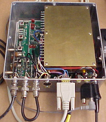
For those that
don't have the QST articles, here is a peek inside a DSP-10. This
one was carefully crafted by Ernie Manly, W7LHL, and is being
used on the air. The brass covered box holds the EZ-Kit Lite DSP.
The main PC board is at the bottom of the box.
Click on the image for a full size screen shot (W7SLB photo).
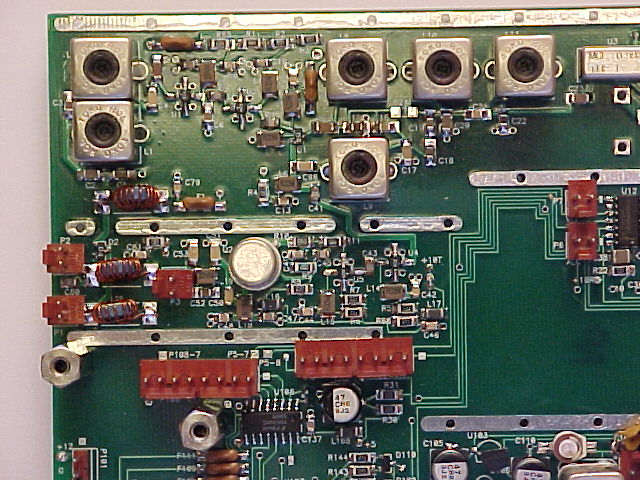
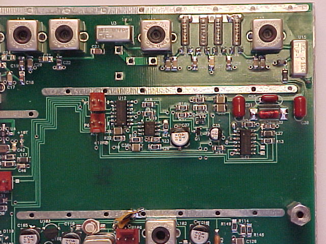
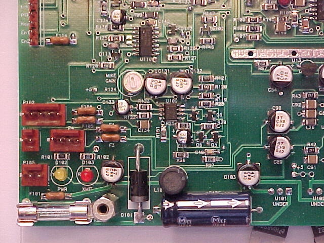
To aid with assembly, W7SLB took detailed pictures of his assembled PC board. Ignore the MOSFETs, Q105 and Q106, in the lower right picture, as these are not the specified package. The board has been divided into four parts. Click on any of the little pictures for the corner that you want to see:
Screen Shot
As a sample of
the front panel, here is a shot by W7SZ of the full transceiver,
using 2.0 software to receive W7PUA on 10 GHz. The path is about
100 miles, home station-to-home station, with a number of hills
in the way. The signal was being scattered by water/ice or
irregularities in the troposphere that produced about 45 Hertz of
Doppler as well as spectral spreading. The sky was hazy with no
rain in the path. At the bottom of the waterfall is a PUA43
message, producing the text at the top. The upper portion of the
waterfall is at a 1200 Hz scale and the PUA43 portion is at a
4800 Hz width. Click on the image for a full size screen shot.
Audio Processor
The full function Audio Processor is available in the DSP-10 software. It supports all modes and transmit as well as receive. This means that special capabilities, such as LTI, PUA43 or EME2, are available with out building the RF hardware. The drawback is that you are at the mercy of the stability and frequency control of the transceiver being used. Also, there is no provision for controlling the transceiver from the DSP-10 Audio Processor. The software is identical for RF and Audio Processor, with the processor being selected by CTRL-ALT-O or o (not zero).
For receive functions, the input to the DSP board comes from the transceiver headphone jack, or equivalent. For transmit functions, the audio output from the DSP board is run into the microphone input of a SSB transceiver. This is a good general purpose audio processor with all the display of a built-in spectrum analyzer. In addition, the input can be tuned up to at least 20 kHz and serves as a general purpose test instrument. The relative dB calibration is excellent.
The audio processor requires either a DSPx & KDSP10 combination, or an EZ-KIT Lite, but no other hardware outside of a PC.
Here is a
sample of the front panel with the audio processor (running the
Ver 1.6 software).
Click on the image for a full sized screen shot.
This page was last updated 27 June 2018, Added Fast PTT Info, W7PUA
Please email comments or corrections to bob 'the at sign' janbob dot com