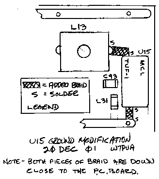
DSP-10: U15 Mixer Ground Modification
Improves the Receiver Sensitivity by increasing the 2nd Mixer LO-RF Isolation
The problem: The second mixer, U15, has its input signal fed from the 19.665 MHz crystal filter. The changing impedance of the filter at the 19.680 MHz LO frequency, along with the LO-RF isolation of the mixer, makes an FM detector. It is not a very good detector, but adequate to find the phase noise on the 19.68 MHz LO. The QST article had the mixers mounted under the PC board. The final PC board had them on top. This turns out to be a factor in the isolation of the TUF-1 mixer, making the problem worse for the mixers on top of the board.
The reduced isolation ends up adding noise to the receiver I-F. The effect is largest at the lowest 3rd I-F frequency (near 10 kHz). This, in turn, just clobbers the overall sensitivity/noise figure.
We will first test the level of the phase noise before modification, and then show how to modify the mixer ground to greatly improve the LO-RF isolation (by about 10 dB).
The test:
  Antenna    Either a 50 Ohm load or leave the connector open
  Freq       146.159700 MHz
  Mode       LSB
  Spec Ave   36
  SpecAnal   Non 4800  (No windowing, 4800 Hz width)
  Offset dB  0       (Upper right corner of upper spectral display)
  dB/div     2
With the RF gain at 100, read the average of trace in the upper spectrum box, at 1000 Hz. Use the scale on the left that runs from 0 to 16 although 0, 2 and 16 don't show. If the trace is off the top of the display, you will need to move it down by a - dB Offset (Alt-2). You want the trace to be generally between the 8 and 16 level. Now change the RF Gain (Shift-F7, Shift-F8) to 64. This essentially removes the noise input to the U15 mixer. Measure the level again at 1000 Hz. The difference in the trace levels between the 100 and 64 RF Gain settings is a measure of the amount of phase noise at the output of the mixer.
If the difference between the trace levels is 3 dB or more, the phase noise is not a problem. If it is less than that amount, perhaps even less than 1 dB, the fix is called for. If there is any question about the level, go ahead with the modification, as it cannot be detrimental.
Modification (two methods, depending on the state of construction):

FOR COMPLETED DSP-10's, you can improve the isolation a lot by getting a REALLY GOOD GROUND on the U15 TUF-1 mixer case. The sketch shows how to do this. 1-There is a ground strip running between U15 and C30. Connect a piece of metal or braid, such as Solder-Wick, between the ground hole by C30 and the case of the mixer. This should be down very close to the board. 2-Do the same thing on the other end of the mixer. Put a piece of metal or braid along the board from the ground hole of L13 to the case of the mixer. Both of these need to be short and heavy. There is already a ground wire on the mixer and it is not good enough. Note that this change does NOT require removing the board from the box or taking the EZKit board out.
FOR DSP-10s BEING BUILT, put the U15 mixer on the back of the board. It can sit against the board with the pins bent at right angles. To make the pin connections short, orient the case so that it is at the edge of the board. It should just cover the edge of the word "COAX" and the end of the mixer should just barely be visible from the top of the board. If your board has green solder mask on the bottom you wiil need to scrape it away under the mixer. This can be done with the edge of a small knife. Then solder BOTH ends of the case to the ground plane of the PC board. This is the way that the original board was, as can be seen in the cover picture of November 1999 QST. I just never realized it would make such a difference to have a 1/16 inch ground lead!
FOR EVERYONE, now re-measure the noise and find the difference in the trace level at 1000 Hz with the RF Gain change. A 3 to 5 dB difference indicates that the full sensitivity is being achieved and a noise figure of about 6 dB should exist.
This has been tested on about several DSP-10s' and similar results have been achieved on all of them. If you are getting less than 3 dB of difference, the problem is either excessive phase-noise detection, or inadequate gain ahead of U15 mixer. Areas to check are:
  1-Amplifiers U1 and U2 check the DC levels.
  2-PIN Diode D1 - be sure the voltage at RF Gain=100 is about 0.75 V
  3-Filter L8-to-L11. Poor alignment or wrong caps.
  4-Crystal Filter aligment, L12 and L13 or wrong caps.
  5-Something not soldered?  Can't happen?
  6-Low 1st or 2nd LO level
Of course, you can also transmit through these components. This may give some clues as to where the signal is being lost.
Finally, after the difference in trace values is adequate, it is a good idea to check the overall gain of the DSP-10 in receive by observing the noise level with all the same settings and the RF Gain at 100. With the dB offset set to zero (it shows 'blank' in the upper right corner), the trace at 1000 Hz should be in the 6 to 10 dB range. Values far from this indicate a problem. This is a test all the way from U1 to and including the A/D converter.
This was prepared 20 Dec 2001. Bob Larkin, W7PUA