DSP-10 from W7PUA: Tips and Measurements
Supplements the Tuneup in the QST articles.
Collected here are various tips on testing the DSP-10 transceiver and measurements that might be an aid to obtaining proper operation. The basic tuneup is in October QST magazine and should be read before using these measurements.
Preliminaries
1-Be sure that the variable named 'hardware' has a value 1, by having a line
in the UHFA.CFG file, such as, 'hardware=1' or 'hardware 1'.
2-The PC program must running as an RF processor (Alt-I or i).
3-Tune the radio to 146.000 MHz (various modifiers along with F9 and F10).
Program Loading There is some general information about program loading in the software 'read me' notes. But, it here are a few tips may be handy:
- The Analog Devices standard extension for DSP loadable files is .EXE. You're right, this makes it impossible to tell them from DOS .exe files. The biggest difference is that if you type their file name followed by an (Enter), DOS will most likely blow up! They need a loader program, such as EZFAST.
- EZFAST is available from the Analog Devices FTP site It is tucked into 'ezkforum.zip'. Also read 'ezkforum.txt.'
- It is very handy to put the loading operations in batch files. The
following batch files from KD7TS are typical of how to use these to load the
EZ-Kit followed by the PC program (he uses serial COM 1):
Contents of ASD.BAT
    SET TZ=PST8
    EZFAST 1 UHF3.EXE G
    UHFA 1
This, of course, is executed by typing at the DOS prompt
    ASD (Enter)
and the following are in the same directory as ASD.BAT
    ASD.BAT
    UHFA.EXE
    UHFA.CFG
    UHF3.EXE
    EZFAST.COM
    EGAVGA.BGI
    GNU_GPL.TXT
He uses EZLD.COM for the various diagnostics programs with another batch file. For instance:
Contents of DIAG.BAT loads the DSP program UDIAG1.EXE EZLD 1 UDIAG1.EXE G - EZFAST speeds the DSP loading process by changing the Baud rate in the serial link. If you have problems with that loader, use either the Windows loader furnished with the EZ-Kit, or the Dwight Elvey standard speed loader EZLD, that runs in DOS. Also note that there are several options available with EZFAST that may be useful in debugging. See the documentation that comes with EZFAST for the details.
- If you don't have EZLD.COM, you can download it here.
Quiet Receiver One of the useful measures of the receiver is the no-input noise level. This is obtained by placing 50 Ohms across the antenna input and measuring the output level. Since the radio has a built-in spectrum analyzer, we can use this to measure the output noise. First setup the following parameters to make sure that my radio and yours are measuring the same things:
Contrast       20
Brightness     70
Mode          USB
Spec Ave       12
Window      BH-92
RF Gain       100
Frequency 145.999
dB/div          5   (Alt-Shift !)
dB Offset      10   (Alt-Shift @ and Alt-Shift #)
The resulting noise for these conditions is shown in the Quiet Input for Full Gain. Note that a signal is present at about -140 dBm. This is barely audible, but shows up well on the spectral display. It is a minor annoyance, and appears every 5 kHz across the band. A software fix for this will be available soon (12 June 00). Meanwhile, note that it is the only birdie (that I have found so far) and that it is very weak! The noise is at about -150 dBm on the display and creates the grass across the spectrum.
Now reduce the RF Gain to 64 (Shift F7) and I saw the following: Quiet Input for RF Gain=64. Note that the signal is still present. The S-meter shows it to be about 36dB stronger, since it did not come through the rf input it was not attenuated by the RF Gain control. The software corrects for the change in RF gain and makes the birdie appear 36 dB stronger than it really is. The noise did drop, though. You should see similar amounts of noise as shown here.
Some Scope Measurements If you have access to a good scope and a signal generator, the following may be useful. Some of the measurements are difficult, as the signals are not big, and/or the frequencies high.
At an RF Input of -30 dBm:
1st RF Amp Output           80 mV p-p
2nd RF Amp Output          650 mV p-p
RF 4-pole filter in        630 mV
This is past overload of the I-F amplifier, for full RF Gain,
so further measurements are not useful.

At  -80 dBm Input:
U10A, pin 1, 15 kHz        130 mV p-p

At -60 dBm Input:
Top of C30                 580 uV p-p
Top of C31                 1.4 mV p-p
U10A, pin 1               1.32 V  p-p

At any input, or no input:
126 MHz LO at U3           600 mV p-p
19.68 LO at U15            650 mV p-p
By listening to the output, one can tell when the A/D converter
goes into overload. The tone sounds raspy and is indeed distorted.
This level was measured as:
Full RF Gain     -56 dBm (350 microvolts)
RF Gain=64       -26 dBm (11,200 microvolts)
Simple RF Voltage Probe If you don't have access to a scope, or would like a cross check on measurements, here are some Voltages that were measured with a simple Voltage Probe and a DVM. But, first some construction details, so that your probe and mine could be as similar as possible. In particular, the lead lengths can be a problem. Here is my simple construction method for the probe:
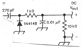
The schematic shows that this probe is almost like the one in October 99 QST except that we do not have a 51 Ohm input termination resistor. The input is on the left and the 270 pF capacitor and ground are the input points. The 10K resistor cuts the sensitivity of the probe a bit, but it helps to make the Voltage independent of the particular DC Voltmeter being used on the output. The 270pF capacitor is what I grabbed out of the drawer. It is fine for frequencies down to about 10 MHz. Larger values are OK as well. Note that with a capacitor on the input, one can use this probe on spots with DC as well as the RF Voltage.
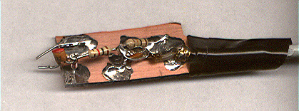
It is built on a scrap of PC board. The #22 tinned wire probe leads are about 1/4-inch (6mm) long. They can be bent to fit the spot being probed, as it is important to get a good short ground connection. I used small coax to run to the DVM, as can be seen on the right. The diode is at the left edge and hard to see. Both resistors are 1/4 Watt.
The measurements were made by probing across some small components. For instance, to measure the RF Voltage at the VCO input to U104, I put the probe right on C146. The little pieces of wire are bent to fit. To measure U105 MSA amplifier output, the probe goes between one of the ground pins of the MMIC and the output pin. This is about the same distance as going across a chip capacitor.
Remember, this is the result of measuring one working unit. I have a second board and will try to confirm these measurements soon. Also, measurements like 6 or 9 mV are close to the conduction point of the silicon diode in the probe, and therefore prone to greater errors than the higher Voltages.
Some Measurements with the probe, all in milliVolts, DC (1/1000 Volt):
  U105-1 Input       9 mV
  U105-3 Output    260 mV
  U106-3 Output    390 mV
  Across C125      190 mV
  Across C146      385 mV
  U3-4 LO Terminal  55 mV
  U8-1 Input        85 mV
  U8-3 Output      970 mV
  U9-3 Output       90 mV
  U15-4 LO Terminal  6 mV
  Across C75       730 mV
This was revised 12 June 00. Bob Larkin, W7PUA