DSP-10 from W7PUA: PLL Diagnostics
Supplements the Tuneup in the QST articles.
Collected here are hints to aid in trouble shooting the phase-locked synthesizers of the DSP-10. I will attempt to have some order to these, but they cannot be used as a step-by-step guide. Read through them and use them as an aid. The basic tuneup is in October QST magazine and should be read first.
Introduction The two phase-locked loops (PLL) are used to generate the conversion frequencies. In order make these work, it should only be necessary to put the voltage-tuned oscillator (VCO) on frequency. The procedure for this is in QST for October, p40. If there are problems, the PLL are a bit difficult to trouble shoot. The following information is directed towards finding problems if the simple tuning procedure does not work. Also, there are more measurements on the Tips and Measurements page.
Preliminaries First, we need to have the board in a known state. This is normally done by a combination of the DSP and the PC programs. In order to simplify the procedure a special program is available
that does only the PLL tests. It runs in the DSP alone. To use this, first be sure that the EZ-Kit is reset by using the RESET button. This takes several seconds, possibly with annoying music. Then load the diagnostic program, udiag2.exe, into the EZ-Kit DSP using either EZLD, EZFAST or the Analog Devices Windows loader. Set this to Go (run the program) at program location 0.This program will do nothing for about 5 seconds, then it programs U104 for 126.000 MHz and U7 for 19.680 MHz. Nothing happens after this, except that the FL1 red LED on the EZ-Kit is an indicator of lock. If BOTH loops are locked, the LED will go out. If either is out of lock it will be red. There is a very brief flicker of the red LED at the end of the 5 seconds, during the time that the two PLL's are achieving lock.
DC Checks After loading the diagnostic program, check the Voltages in October QST, Table 1. In addition, check the following:
  U104-3       5.0 Volts
  U104-4       5.0 Volts
  U7-16        4.9 Volts
  Across R44  0.14 Volts
  U105-1 In    1.3 Volts
  U106-1 In    1.3 Volts
  U8-1 In      1.5 Volts
  U9-1 In      1.5 Volts
  U104-7         5 Volts    This means LD=Lock; 0 to 4V=Out-of-Lock
  U7-11          5 Volts    This means LD=Lock; 0 to 4V=Out-of-Lock
Your Voltmeter probably has more digits than I show here, but we really don't need 3 or 4 digits. There are always some variations between units, and we only want to make sure the voltages are reasonable. If I measured 0.14 Volts and you get 0.15, we have no concerns. If you measure 0.25, most likely somthing is wrong. Experience shows that most problems in a circuit will be reflected in an erroneous DC Voltage.
Be aware in checking some of these points, that there is RF on some of them, such as the MSA amplifier outputs. This may cause some difference in the voltages observed.
Serial Programming There are two sets of serial communications from the DSP to the main board. They share the data and clock lines, but have separate enable lines. Because of differences in manufacturers programming requirements, they also use different signalling techniques.
U7 has its own enable. Details on the 'Bit-Grabber' programming is in the data sheet for the MC145170.
U104 is programmed along with the two shift registers, U107 and U108. This is a help if things are not correct. We can see the results of programming the shift registers with a Voltmeter:
The following will be programmed by the udiag2.exe program
  U107-15  0 V
  U107-1   0 V
  U107-2   0 V
  U107-3   5 V
  U107-4   0 V
  U107-5   0 V
  U107-6   0 V
  U107-7   5 V

  U108-15  0 V
  U108-1   0 V
  U108-2   5 V
  U108-3   0 V
  U108-4   0 V
  U108-5   0 V
  U108-6   0 V
  U108-7   0 V
If this pattern is not observed, it is highly unlikely that U104 will program properly. Go back and check out the serial programming portions of the board. Details for this are given in October QST and on the web page Serial Diagnostics.
10 MHz Signals Next we confirm that the 10 MHz reference is feeding both PLL's. If you have a scope good to more than 10 MHz, this is easy. Compare the waveform you have at U7-1 with that shown below in diag2a.jpg. It should be similar.
If you do not have a scope available, you can try measuring U7-1 with a DC Voltmeter. You should see the average Voltage of about 2.5 Volts. If it is close to 0 or to 5 Volts there is a problem.
Problems with the 10 MHz signal might be related to the coax W29 on the back of the board.
Next we need to be sure that the 10 MHz reference is working. You must have either a 10 MHz crystal in place and a jumper between P106-1 and P106-2 (the side toward the crystal,) or be running an external 10 MHz reference to P106-2 and P106-3(ground.)
124-128 MHz PLL Next work on getting U104, the 126 MHz PLL working. Check the VCO frequency, if you have some method of receiving that frequency. A receiver that covers the aircraft frequencies, a counter connected to the mixer side of C127, or a spectrum analyzer would all work. If you do not have an easy method of finding the VCO frequency see the 'indirect method' below. If the synthesizer is running at 126 MHz, check the VCO control Voltage at U104-5 (or at the top of R104.) This Voltage should be about 1 Volt and is set by L102.
If this Voltage is near 0 or 5 Volts, temporarily connect a ground to the the junction of R105 and C113. The VCO frequency, as set by L102, should be about 123.5 MHz. If not look for problems with C117, C118, C141, L102 or the tuning diodes.
An update as of 4 Dec 99: Based on about 3 boards, the Q101 VCO's are tuning at or very near their their highest frequency. It is acceptable to remove the core from L102 if this works. In this case one can alter the frequency some by changing the number of turns on L103. Another trick that worked for KD7TS is to cut down the length of the tuning core by a few threads. This allows the core to go in farther, thus tuning higher in frequency. If you cant't tune high enough, it will be necessary to change C117 from 10 to 8.2 or even 6.8 pF.
19.68 MHz PLL Again try to determine that the VCO will cover the 19.68 MHz frequency. C70 or C71 may be incorrect. Waveforms are shown below, if you have access to a suitable 'scope.
To adjust L21, check the tuning voltage at the output of U6. It should be possible to have it near mid-range (abt 4V) and it should tune with C69. If the voltage is always high, around 9V, spread the turns on L21. If low, squeeze them. If you have something that tunes 19.68 MHz it would be a good check on the operation of the synthesizer, but that is really not necessary. The important check is the ability to get the tuning Voltage at the output of U6 and see if you can move it either side of 4 Volts, using C69.
PLL Performance Checks To check the operation of the PLL's:
The following 4 pulses are 0 V most of the time and go to 5 V when pulsing.
U104-14 is available at the test pad next to the IC. It is the signal (programable divider output) input to the phase detector, and should be a positive going pulse, about 500 nS wide, repeating every 200 microseconds (5000 times per second.) See the waveform pictures below.
U104-13 is available at the test pad away from the IC. It is the reference input to the phase detector, and should be a positive going pulse, about 100 nS wide, repeating every 200 microseconds (5000 times per second.) See the waveform pictures below.
U7-9 is available at the IC. It is the reference input to the phase detector, and should be a positive going pulse, about 450 nS wide repeating every 50 microseconds (20,000 times per second.)
U7-10 is available at the IC. It is the signal (divide by N) input to the phase detector, and should be a positive going pulse, about 1.75 microseconds wide repeating every 50 microseconds (20,000 times per second.)
For both IC's, the leading edges (positive going) of the signal and reference are in time alignment.
A Note on Coil Tuning The tuning slug in L102 (as with all the Toko 10K coils) goes towards minimum L at the bottom of the can. The inductance also goes down if you unscrew the slug, but the it gets loose and unreliable. You should go to min L by putting the slug into the core. Min L (highest frequency) is just as it hits the board. Max L (lowest frequency) is when the slug is flush with the top of the can. For my 126 MHz VCO, L102 tunes with the slug about 0.15 inches below the top of the can.
The Indirect Method of Finding the 126 MHz VCO Frequency If you do not have any method for measuring the 126 MHz VCO frequency, it is still possible to deduce the frequency by watching the lock range as the receiver frequency is changed. Keep the following in mind. The 126 MHz PLL operates within 2.5 kHz of the dial frequency, minus 19.665 MHz. And, there are no software limits to the dial frequency.
By watching the Dial range over which it is possible to maintain phase lock, we can determine the tuning range of the VCO. In fact, you really don't care about the VCO frequency in the end. You only want to be able to tune 144 to 148 MHz with some extra. The following outlines the procedure:
1-Load the standard UHF3 and UHFA programs for the DSP and PC.
2-Make sure you are in RF operation and that hardware=1 is in
  the UHFA.CFG file.
3-The serial hardware programming and RS-232 circuits all must
  be working.
4-Attach a Voltmeter to the junction of R145 and U104-7 to
  indicate Lock. A Voltage near 5 indicates Lock, while 0 to 4
  is No Lock.
5-Tune the receiver in either 100 KHz steps (Ctrl-Alt-F9 and F10)
  or 1 MHz steps (Ctrl-Shift-F9 or F10) while watching the
  Voltmeter. Try both directions from 146 MHz to find where Lock
  occurs. The goal then is to have the Lock Range centered for
  tuning from 144 to 148 MHz. The actual VCO frequency will then
  be 19.665 MHz less.
Measured Waveforms
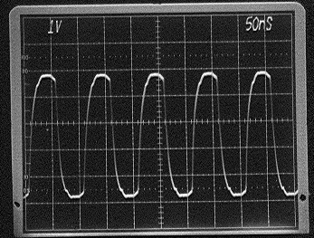
This waveform is the 10 MHz signal measured at U7-1. Zero volts is 1 division from the bottom (on all 4 pix), where the little black marks are on the sides. This is measured with a 250 MHz scope and lower freq scopes might have different results. The Volts/div and time/div are shown on the screen. A nS is a thousand's of a microsecond.
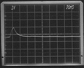
This is the output of the U7 phase detector, U7-13. This is a very small pulse and hard to see. It repeats every 50 microseconds.
This is the lock detect from U7 at U7-11. It is little easier to see, being about 50 nsec wide. It repeats every 50 microseconds. When out of lock, it is low much more.
This waveform is the lock detect for U104 at U104-7. This repeats every 200 microseconds. When out of lock it is low much more.
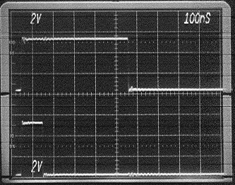
These waveforms are the two inputs to the 126 MHz phase detector in U104. At the top is U104-14 which is the programable divider output. Below this is the reference input to the phase detector, U104-13. Both of these occur every 200 microseconds. The zero Voltage points are again marked at the edge of the photo. Note that since the PLL is locked, the leading edges of the two waveforms are in time alignment.
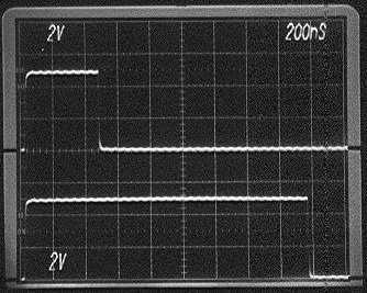
These waveforms are the two inputs to the 19.68 MHz phase detector in U7. At the top is U7-9 which is the reference input. Below this is the programable divider (from the VCO) input at U7-10. Both of these occur every 50 microseconds. The zero Voltage points are again marked at the edge of the photo. Note that since the PLL is locked, the leading edges of the two waveforms are in time alignment.
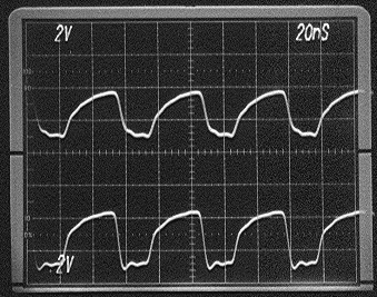
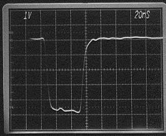
The top trace is the U7-4 VCO input to the 19.68 MHz PLL IC. It is fed from U8 and the lower waveform is the U8 output, U8-3. The rf amplifier is running at full output, as reflected by the clipping at the bottom of the waveform. Zero Volts for the two measurments are the marks on the side of the picture. (Corrected, U8 reference was U5, 12 June 00).
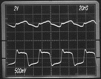
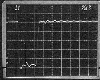
The top trace is the output of U9, U9-3, that supplies the 19.68 MHz LO to mixer U15. The bottom trace is the mixer LO input, U15-4. Note the scale change on the lower trace, and also that the zero-Voltage point has been moved up, since there is no DC Voltage at that point. Also note that these two traces are almost the same point, seaprated by one blocking capacitor and a few inches of coax. The clipping action of the mixer is still more evident in the lower trace than the upper one. Also, if you calculate the apparent power in these traces, it is quite a bit below 7 dBm. That is due, again, to the clipping of the mixer diodes.
This was lastrevised 12 June 00. Bob Larkin, W7PUA