1 - Low Pass
2 - High Pass
3 - Band Pass of the alternating parallel/series LC topology
4 - Band Reject of the same general topology but with series/shunt reversed
5 - Band Pass of the Cohn type, with capacitive top coupling.
The pass band can have either a Butterworth or Chebyshev shape using built-in design equations. Alternatively, one can input any other low pass prototype in normalized form. The program uses no graphics. It does only the design phase of filters and not the analysis phase. I use ARRL RF Designer for analysis. Other alternatives are available.
This page has the program for download and a general discussion of how it is used. There are several pages linked below that show specific examples of designs, including a few hints about use of particular filter types.
Program Useage - Step one is to obtain the SmallBasic program. Information on this is available on-line. Be sure to get the version that has been compiled for either Linux or Windows, as you use. Next, create a directory anywhere that will hold the LCFIL3A.BAS program, as well as data files created by the program. Download the LCFIL3A.BAS from the download link below to that directory. SmallBasic is executed either from a desktop icon or from program launchers for the operating system being used. Within SmallBasic, use the menu path Files/Load to navigate to the LCFIL3A.BAS program. Next go to the LCFIL3A tab, and then menu item Program/Run.
A note - do not confuse SmallBasic with a Microsoft product, "Small Basic." They are not the same at all.
An aside is that you may at times think the program is not responding to keyboard or mouse. This will not happen when the program prompts are happening, but can after the program stops. Basic allows for continuing operator interaction, which can be convenient for debugging. To completely stop the program use the menu item Program/Break. This will, for instance, allow you to Program/Run the program again to design another filter.
Designing a filter -
After you use Program/Run, the program produces a couple of lines of sign-on, as:

The first step in the design of any of the filter types is the "low pass prototype." This is a low pass filter that works at an impedance of 1 Ohm and has a cut off frequency of 1/(2*pi) Hz. This is a low frequency, about 0.159 Hz, but is chosen because it simplifies some of the later math. Components end up with values in the general range of 1 Hy for inductors, and 1 Farad for capacitors. The shape of the response is frequency scaled for a final low pass filter. For high pass filters, the general shape is reversed about the cutoff frequency. Similar scaling operations occur for band pass and band reject filters.
In the initial dialog that follows, the first item allows for an output file. This places all of the numerical data, but not all of the explanatory material, onto a file called LCFIL.TXT. This file is located in the same directory as the .BAS program. It is always appended to, and never cleared. Thus the latest data is at the bottom end of the file. You may want to clear or delete the file, at times, when the data is no longer needed.
The data entry for the prototype filter is:

The number of elements in the LPF ends up as the number of LC
resonators in the band pass or band reject filters. This changes
the rate of cutoff of the filter in the stop bands. The ripple is a somewhat
lengthy topic. More ripple allows a faster rate of cutoff outside the pass band,
but also causes both variation in the amplitude response and higher levels
of reflected power, and SWR, in the pass band. The judgements, trade-offs and
relationships between the parameters are part of the design process. Fortunately,
it is easy to design multiple filters and observe the "experimental" results.
The special case of 0 ripple produces a Butterworth response for the low pass filter, that has no ripple. Chebyshev filters have there low pass band width as the point where the response drops below the ripple level. This obviously does not work for the Butterworth case, and so the 3-dB point is arbitrarily chosen for that case. When comparing bandwidths, be sure to keep in mind the major change in scaling that has occurred.
A -1 input for ripple allows manual input of the low pass prototype values g(j). There are many alternatives to the Chebyshev and Butterworth shapes. Tables of g(j) are tabulated (see reference Zverev, below) for many responses, such as Gaussian or Equal Ripple Phase.
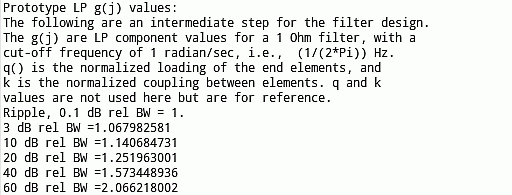
The program next shows a few data points on the low pass response. This is
scaled to either the ripple bandwidth or the 3-dB bandwidth, as indicated
on the screen. Relative bandwidths are given for the 3, 10, 20, 40 and 60
dB points:

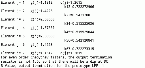
The component values for the prototype filter are the N g(j) as listed
in the output:

In addition there are two values of q, one for the input and one for the output, plus N-1 coupling numbers, k(j,j+1). These k and q vales are shown to the right of the g(j) values, The q and k values are not used in this program, but are needed for alternative design methods (see references below).
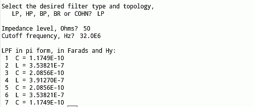
Now the program will shift the impedance up to
a useful value,and also scale the frequencies to useful regions. These values
are requested and the scaled components are listed:

Note that the units for the capacitors and inductors are Farads and Henrys. This takes some thinking, but makes the program much simpler. The issue is that the frequencies can range from audio to microwaves and the impedances can be Ohms to kilo-Ohms. The easy way to deal with this huge range of numbers is to use exponential (Scientific)) notation. The basic form x.xxxxEnnn says that you take the number x.xxxx and shift the decimal point to the right by nnn places. If nnn is negative the decimal point moves to the left. This means that a pF is 1.0000E-12 and a micro Henry is 1.0000E-6. Incidentally, input frequencies (or other inputs) can be in the same form. Thus, 32 MHz is 3.200E7 or since the language is flexible, you can equally well input 32.00E6, thinking of E6 as MHz. For inputs, the trailing zeros are not required. 32E6 is a valid input, as is 32.0000000000E6.
Several Examples -
The following examples show program interaction, and also gives some hints about
the electronic questions associated with filters. These include the computed
responses, in some cases.
32 MHz 7-Element Low Pass Filter
125 MHz 13-Element Butterworth High Pass Filter
10 to 15 MHz 7-Resonator Band Pass Filter
3.5 to 4.0 MHz 5-Resonator Band Reject Filter
5.4 to 5.6 MHz 3-Pole Top-Coupled Band Pass Filter
Download - Here is the Basic program, ready to run under SmallBasic:
References
As you might expect, these references go back a bit. All classic stuff,
though, and well worthy of space on the bookshelf.
This page was issued, and Copyrighted 10 December 2013, Robert S. Larkin
This page was updated, and Copyrighted 14 June 2021, Robert S. Larkin
Please email comments or corrections to bob 'the at
sign' janbob dot com
LCFIL3A.BAS Filter design program.
This is best downloaded through a right-click option to save the file.
1 - Anatol I. Zverev, "Handbook of Filter Synthesis," John Wiley and Sons, 19967. Fabulous
    compilation of data and methods.
2 - Thomas R. Cuthbert, "Circuit Design Using Personal Computers," John Wiley and Sons, 1983.
    This book has "heavy-weight" information, complete with some Basic programs. A Cuthbert
    program is used in LCFIL3 to calculate filter insertion loss.
3 - Wesley H. Hayward, "Introduction to Radio Frequency Design," Prentice-Hall (later ARRL)
    1982. Excellent introduction to modern filter design, as well as ladder analysis.
4 - Wes Hayward, Rick Campbell and Bob Larkin, "Experimental Methods in RF Design," ARRL 2003.
    Chapter 3 has the shortened hands-on version of ref 3
5 - Seymour B. Cohn, "Direct Coupled Resonator Filters," Proceedings IRE, Feb 1957.
    This is where modern filter design and direct-coupled filters converged.
    It has the design equations for top-coupled band pass filters.