The component values for the 5 resonant circuits are at the bottom of the printout. See the low pass filter description for assistance with the exponential notation of part values.
The schematic show
all of the component values:
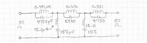
We can simulate the overall response:
This plot shows the insertion loss in a 50-Ohm system as the red curve, MS21 or "magnitude of S21>" It also shows in blue the magnitude of the reflected wave, MS11. This latter quantity, shown in dB is a measure of the impedance match looking into one port of the filter with the other port terminated in 50 Ohms. The curves correspond to lossless components.
At first glance, this looks like a band pass filter. But, the red
curve is the MS21 and it has much attenuation from 3.5 to 4.0 MHz! Again,
component losses will cause the most ainsertion loss at the edges next
to the stop band.
Click here
to return to the main LCFIL3A page.
This page was last updated and Copyrighted 11 December 2013, Robert S. Larkin
Please email comments or corrections to bob 'the at
sign' janbob dot com