The schematic show
all of the values:
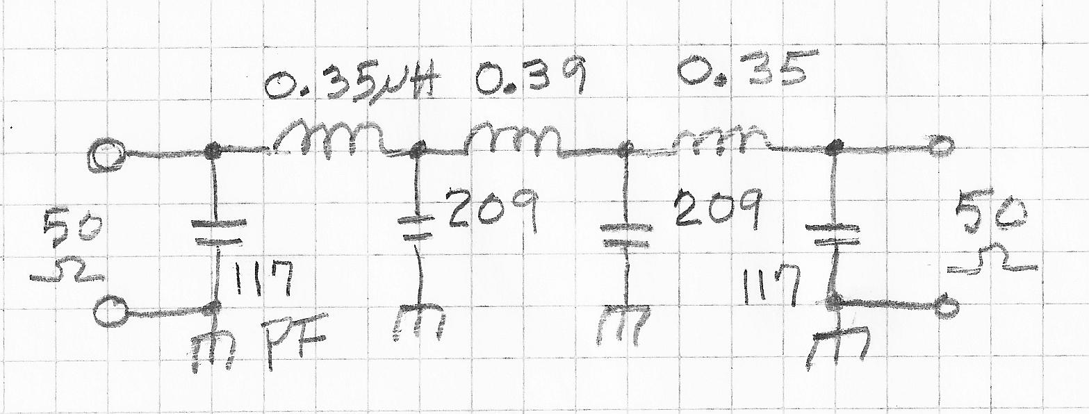
At this point, we might just assemble the parts per the schematic, being
careful to avoid stray coupling between the inductors. We could then check
the response using a signal generator and a sensitive detector. This would
likely result in a low pass working much as we expect, and suitable for
a chore such as limiting the spectra of a HF transmitter. Alternatively,
having a facility to predict the frequency response can in some cases
save time, since simulation is generally faster than building of
prototypes. In addition, if problems are uncovered in simulation, it may
also suggest solutions to the problems. So, here is the predicted response of
our 7-element filter, assuming that all components are lossless:
This plot shows the insertion loss in a 50-Ohm system as the red curve, MS21 or "magnitude of S21>" It also shows in blue the magnitude of the reflected wave, MS11. This latter quantity, shown in dB is a measure of the impedance match looking into one port of the filter with the other port terminated in 50 Ohms. For this example, the peaks in MS11 are at about -16.5 dB, corresponding to a VSWR of about 1.35, or an insertion loss of 0.1 dB. This is the way that the ripples occur. The components being simulated were lossless, so the ripples must come from reflections rather than absorption. An interesting question is, "Why ripples, at all?" In short, accepting ripples in the passband will allow greater reflection loss in the stop band.
So, what if the filter components are not lossless? Lets run the simulation
again, using lossless capacitors, but achieveable inductors
with an unloaded Q of 150. Here is the response:
The scale has been altered to show the passband detail, but looking at the
original scale of plot revealed that general shape had been retained.
MS11 values were not changed much, either. But the detailed look seen
here, shows that the
insertion loss increases by up to 0.2 dB. This increase is greatest
close to the cut-off frequency. The total insertion loss around 30 MHz is
about 0.1 dB for reflection, and 0.2 dB for heating of the inductors.
The low-pass filter would still be a good performer for most applications,
and we could proceed to assemble and test a physical model!
But, that is a different story. Here we are only exploring the LCFIL3A
design program.
Click here
to return to the main LCFIL3A page.
This page was last updated and Copyrighted 10 December 2013, Robert S. Larkin
Please email comments or corrections to bob 'the at
sign' janbob dot com