The component values for the 13 elements are at the bottom of the printout. See the low pass filter description for assistance with the exponential notation of part values.
This is a good time to digress and look at the way that the LP prototype filter is converted to the HP version. As was the case for the low pass filters, there is impedance and frequency scaling of the L and C components. More interesting is the change in topology. Step 1 is to come up with a mapping of frequencies that changes the response to HP. Ages ago, it was found that if one took the equations describing the frequency response of the LP filter, and replaced the frequency variable, f, with a new variable that was equal to 1/f, the desired shape would be obtained. This is called a frequency "mapping" which saves much effort in creating responses other than LP. Step 2 turns out to require replacing LP shunt capacitors with HP series capacitorss and LP series inductors with HP shunt inductors. This produces the mapped frequency response, exactly.
Not surprisingly, the attenuation curve can be predicted, as well. From the print out above, we see that the 40 dB point occurs in the LP response at a frequency 1.42509 times the 3 dB frequency. In the case of the HP filter, the 40 dB point will be at (1/1.42509) = 0.7017 times the 3 dB point, or about 88 MHz.
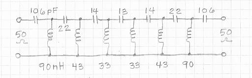
The schematic show
all of the values:
It may be adequate to use this sort of thought process to select an
appropriate HP filter. Or, again as in the LP case, we can simulate the overall
response:
This plot shows the insertion loss in a 50-Ohm system as the red curve, MS21 or "magnitude of S21>" It also shows in blue the magnitude of the reflected wave, MS11. This latter quantity, shown in dB is a measure of the impedance match looking into one port of the filter with the other port terminated in 50 Ohms. It can be seen that the Butterworth response is indeeds smooth without ripples. In order to maintain this respnse in the physical reality, it is important that the component values be precise, and that the terminating impedances be 50 Ohms.
To my perception, this response curve does not seem steep enough for the effort (number of components) required. If the receiver this is to be used with extends up to, say, 500 or 1000 MHz, it may well be the best choice. This simple topology can be costructed with parts that operate close to value over wide bandwidths. If the pass band needed is smaller, say the 140 to 170 MHz originally postulated, one should consider the transformed band pass filter that is designed by LCFIL3A.BAS. That topology allows faster cutoff rates by restricting the pass band size. It also provides high side attenuation that may be useful. Another alternative is to use a HP that includes nulls in the stop band, referred to as "zeros." That filter topology is not designed by LCFIL3A.BAS, but can improve the sharpness of the response considerably. Going to a Chebyshev response would also have some influence on the sharpness of the cutoff, but if the 3-dB point is kept at 125 MHz, it will not be greatly different. That is to say, the Butterworth is a limiting case of a continuim of ripple levels and the overall shape of a 0.01 Chebyshev is very much that of a Butterworth. No "free lunches" are available.
Click here to return to the main LCFIL3A page.
This page was last updated and Copyrighted 11 December 2013, Robert S. Larkin
Please email comments or corrections to bob 'the at sign' janbob dot com