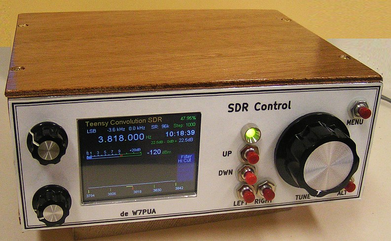
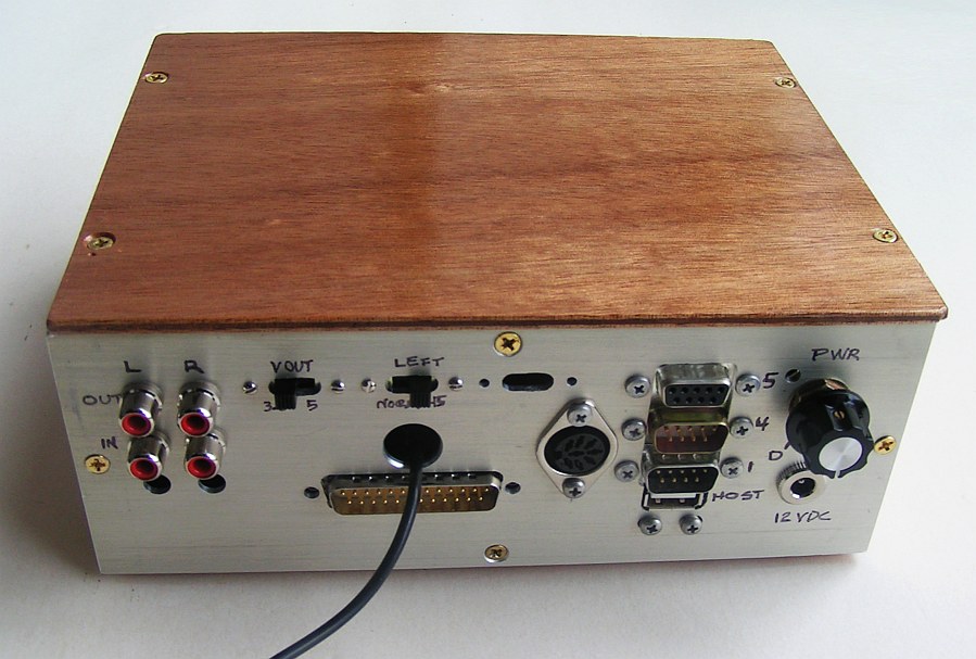
Introduction - It seems like every microcomputer project includes tossing together buttons, knobs and displays, often lying out on a table. This is OK if the project is of short life. But, often what was intended to be a quick demo stays around and the proto wires live on (and get unreliable). This control box is intended to move this process up a bit. It has all the control stuff tucked away in the box and a 25-pin D connector is used to hook to the things being controlled. The primary "things" for me are radio receivers and transmitters. Radio receivers have special needs in that they are very sensitive and pick up noise such as is generated in digital control hardware. So, the D connector becomes the interface between fast and noisy digital operations and the sensitive radio circuits. This allows RF filtering on both sides of this interface, as may be needed.
I never know what sort of control might be needed for the next project. Most of us don't! So in addition to planning for the two projects that are already defined, the board allows for quite a bit of expansion. It is the Swiss Army Knife approach, and ends up with the following:
Note that nothing in this Control Box involves RF signals. That is all accessed via the D connector. Thus if a general Teensy project comes along, it can be plugged in and operated by this hardware user interface. In addition, if the project just involves controlling audio, nothing needs to be plugged into the D connector at all. The Teensy 3.6, Audio Adaptor, display and controls are all ready to be used.
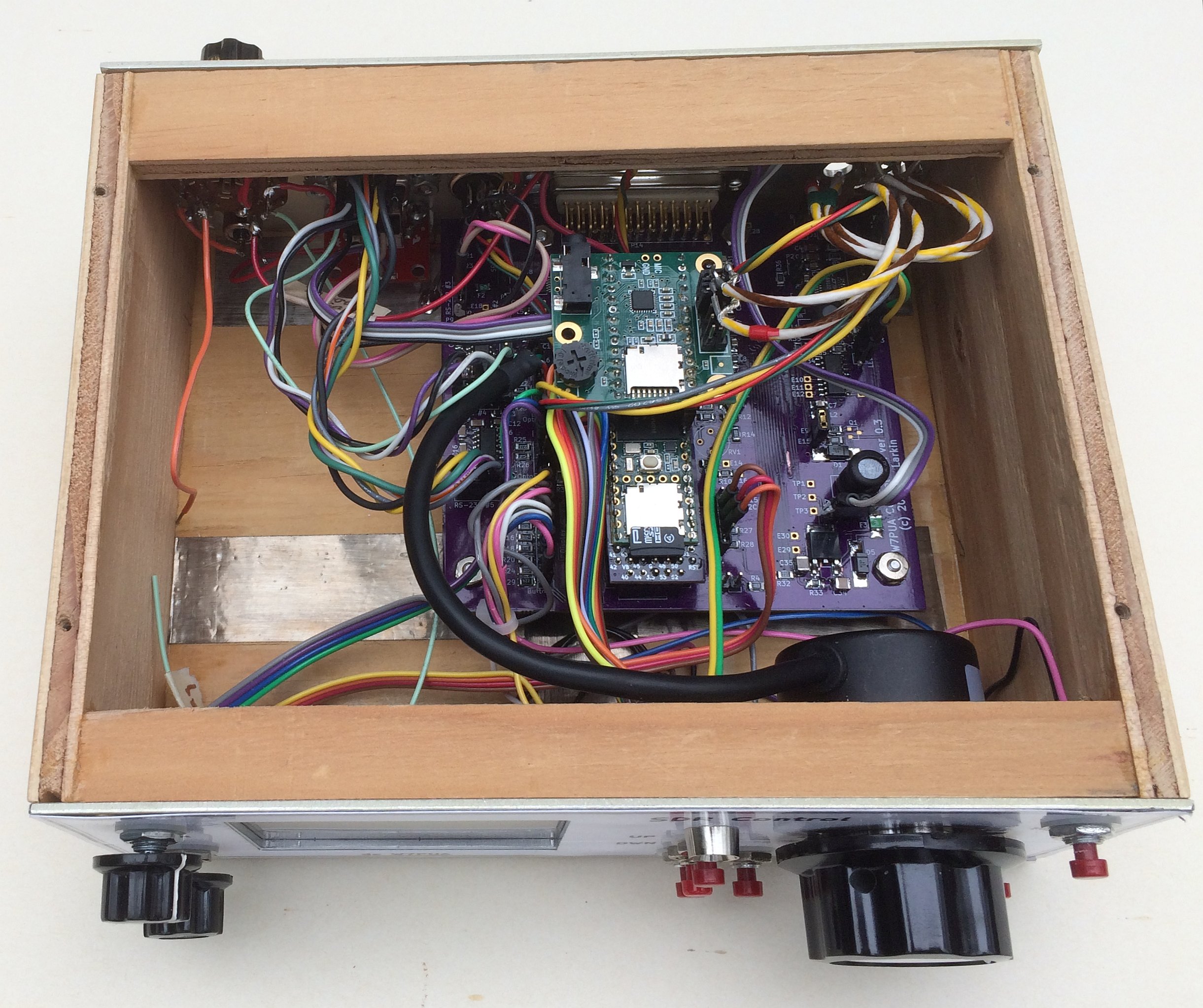
Hardware -The box above uses aluminum front and back panels. The box happens to be constructed of wood, but metal, or even plastic could be used. The non-metal styles use metal adhesive tape to enable shielding and grounding control. With the tape the structural material can be anything. Inside the box is PC Board, about 4x4-inches (100x100 mm). The main function of the board is to hold a bunch of connectors and to connect these up to the Teensy along with suitable driver IC's.
Access to some of the Teensy pins is done by rectangular pads on the bottom of the Teensy board. This is not convenient for making the Teensy plug-in. An extension board is available and discussed here. These boards are available from OSH Park in multiples of 3. To work with this extension, three sets sockets are on the main board in rows of 7, 7 and 5.
Two other connections can be made to the Teensy via pins on that board and sockets on the main board. A set of 5 pins makes the Host USB port available. These come out to a header, P6, on the main board. Similarly, the 5 Volts supplied to the Teensy from a Host PC is accessed by a single pin that goes to pad E41.
The schematic is on four sheets, that are in this .pdf file.
The Part List (BOM) is available as a text file.
This includes ordering info for many parts. There are three rotary encoders that use two different class of parts.
The two Bourns PEC11L-4125F-S0020 are simple mechanical quadrature encoders with steps, and also have a switch that is actuates
by pushing on the knob. These work fine for functions like gain controls and channel selectors, as they have 20 pulses per
revolution.
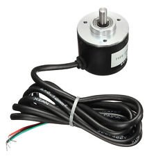 The third encoder, shown on the right, was obtained from ebay. It is very high resolution and has no mechanical
indents. It can be used for tuning functions giving no indication of the data coming in steps.
It has excellent bearings and
such smooth movement as to requiring a friction device for some applications.
This type, shown in the picture, is available from many sources, with some variation in spec's.
They have sold for around 10 to 12 USD. Mine has 360 pulses per rotation for each of I and Q and has a
general description on ebay of: Output is NPN open collector.
For measuring goods angle, acceleration, length measurements and the rotational speed
Small size, light weight, easy to install, cost-effective
Color: Black, Size:5 x 3.7 cm
The third encoder, shown on the right, was obtained from ebay. It is very high resolution and has no mechanical
indents. It can be used for tuning functions giving no indication of the data coming in steps.
It has excellent bearings and
such smooth movement as to requiring a friction device for some applications.
This type, shown in the picture, is available from many sources, with some variation in spec's.
They have sold for around 10 to 12 USD. Mine has 360 pulses per rotation for each of I and Q and has a
general description on ebay of: Output is NPN open collector.
For measuring goods angle, acceleration, length measurements and the rotational speed
Small size, light weight, easy to install, cost-effective
Color: Black, Size:5 x 3.7 cm
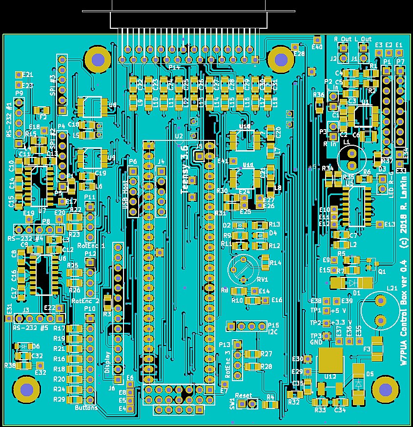
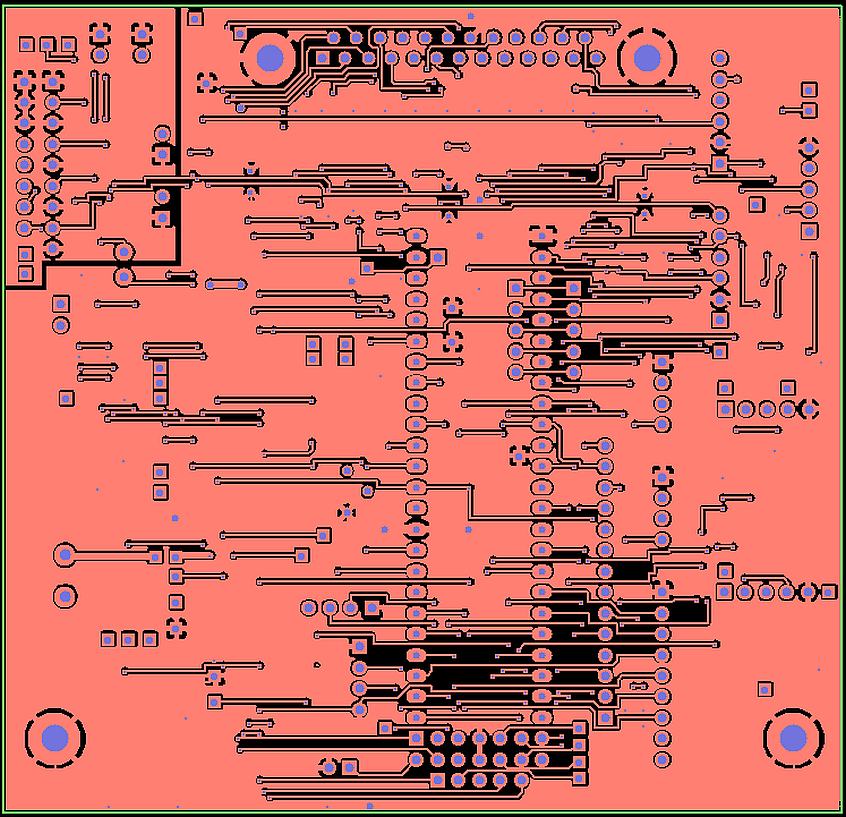
The PC Board is available from OSH Park in multiples of three. The drawing below includes construction markings (such as part outlines). It is useful for seeing what the board is going to look like as well as for supplying assembly information.
Detailed description - Details are available in the Control Box Use document. Included are the various interfaces as well as recommendations for specific SDR's. Be sure to read through and understand this document. There are many options, some you need and some you may not. An example of this is the DC power selection for running this box, which is described in detail.
The discussion here has been mainly about the hardware involved. Obviously the software is also a big part of making things happen. Most of that will need to wait, but to see a bit about using the Box, here is the Control Box test program as a text file. After the PJRC Teensyduino package is added to the Arduino IDE, this .ino file behaves like any other Arduino program (sketch).
Notes:Issued 28 Feb, 2018. Revised: 2 March 2018 Added .ino file. Revised 25 Jan 2019: Added Part List and Rotary Encoder info plus more construction detail. - All Copyright © Robert Larkin 2018