Introduction - Capacitors have always been used to provide a path to ground for high frequency signals on a conductor, while allowing DC or other low frequency signals to pass along the conductor freely. This is referred to as a "bypass" capacitor. Closely related are capacitors used for power filtering applications where they are often combined with series inductors or resistors. Traditionally, wideband bypass capacitors involved electrolytic or tantalum capacitors that suffered from excessive series inductance and resistance at high frequencies. Attempts to solve this issue by paralleling smaller capacitors have been shown to be fundamentally detrimental [note 1]. However, in recent years the manufacturing technology for multilayer ceramic capacitors (MLCC) has produced very high capacity values in small surface-mounted packages [note 3]. These MLCC components offer ways to improve the effectiveness of bypassing by using multiple capacitors all of the same value. While improving circuit performance, this also makes circuits simpler and less costly. This note explores a few fundamental ways to do this.
What not to do - The section of the Experimental Methods book, referenced in note 1, covers the problems associated with building wideband bypass capacitors by paralleling different values. Unless the application is unusual and the implications of paralleling different values has been well studied, the best rule is "to not do it!" A measured example, illustrating the problems is shown in Figure 1.
The impedance plot, Figure 1, is an example of undesired consequences of parallel capacitors. The several peaks in impedance are the result of the inductance associated with a large value capacitor parallel resonating with a smaller capacity. For example, the parallel resonance at about 260 MHz raises the impedance to around 13 Ohms, making the bypass of little effect. In all cases, the parallel and series resonances will alternate as the frequency goes up. In some cases, losses within a capacitor may make the resonance less obvious, but they are present. The next section deals with using multiple identical capacitors to avoid these problems.
Another, not wrong, but out-of-date method of bypassing is to have one or two 470 pF or 0.001uF disc caps placed across the line to be bypassed. This approach became popular in the 1950's when TVI was a big problem. The disc capacitors were 0.25 inches in diameter and had enough lead inductance to have series resonance roughly in the VHF TV spectrum. I dug in the junk box and came up with a pair of 470 pF disc caps and mounted these with short leads (about a tenth inch, each) to a test fixture.
The measured data shows this system to be quite successful at the VHF TV band, around 54 to 216 MHz, where the impedance is below 2-Ohms. The 6 nH of each cap is series resonated with the 470 pF at about 100 MHz. The 2 to 30 MHz impedance is not so good, but for tube equipment, it was probably adequate. On the high side, the impedance was acceptable in the hundreds of MHz. Note that since these two capacitors are identical, the series resonant frequency is the same as would be seen for a single capacitor. For the general applications of these disks caps, the series resonance is a feature. So, they did what was needed, but, as will be shown, with today's miniature devices we can do much better.
More on Unequal Parallel Capacitors - (NEW! This section Added 1 Feb 2025.) Let's explore the paralleling capacitors of unequal value by looking at the details of just 2 capacitors. We will first show data from a series of measurements, and then we will take a quick look at the theory behind the problem. This is an interesting case to look at as almost everywhere you look in electronic circuitry there is a power line being bypassed to ground by 2 or more unequal value capacitors. Typically these could be a 0.01 uF ceramic paralleled by a 0.1 to 1 uF ceramic, or perhaps by a 1, 2.2 or 10 uF tantalum or electrolytic. Explanations often are that bypass capacitors are only effective over a limited frequency range, and by paralleling several values, we will have covered all the frequencies of interest. The opening section of this note says that is not true. Let's see why. As we procede, remember that every real capacitor has some amount of series inductance. That is of key importance.
We will start with a single 0.022 uF ceramic NP0 capacitor across a 50-Ohm transmission line. This 50-Ohm test setup is commonly used to evaluate power filters, in part because it represents the sort of configuration that a power filter encounters, and in part because it is easy to measure. The following are S21 measurements of transmission loss in a 50-Ohm system, measured by a HP8714B network analyzer. Here is the graph for 0.3 to 100 MHz.
At very low frequencies, the attenuation is not particularly great, starting with about 6 dB at 300 KHz. Around 300 KHz, the 25 Ohm capacitive reactance is not effective. The attenuation improves as the frequency gets higher, until a null is reached at about 40 MHz. This is series resonance, with the inherent series inductance cancelling the reactance of the 0.022 uF capacity. At that point the L and C reactances are equal in magnitude and opposite in sign. Based on the resonant frequency and the capacity value, we calculate the series inductance as about 0.7 nH. This low value is possible because the test fixture uses no ground vias and the 0805 chip is soldered directly to the elevated line and to the ground plane.
So, continuing up in frequency, the attenuation is mostly set by this series inductance. If we focus on the region below 40 MHz, we might conclude the attenuation is inadequate. At 10 MHz, we have around 32 dB. Our application might well call for 40 or 50 dB, maybe more. So let us try to improve this by soldering a 0.47 uF high quality film capacitor across the 0.022 chip. Since this is for low frequencies, we casually use a capacitor with leads of a quarter inch or so. The next graph shows the result.
Up to 2.5 MHz, we seem to have made big progress. The more rapid fall of the reactance for the larger capacitance is effective. The 2.5 MHz null is again the series resonance of the 0.47 uF with its leads. But wait, above 2.5 MHz the insertion loss quickly becomes much less and peaks out at 11.2 MHz where the attenuation is only 12.5 dB. This is right where we wanted 40 or 50 dB. What happened? Well, more resonances have occurred. This time it is the series inductance of the 0.47 uF parallel resonating with the 0.022 uF capacity that is still well below its series resonant frequency.
This is not good, but maybe the problem is the capacitor leads and their big inductance. So, away with the leaded capacitor and in with a 0.47 uF 0805 chip, soldered on the same 50-Ohm line, opposite the 0.022 uF. The next graph is the same measurement, but with the two tiny chips.
Well, that moved the frequencies around. But the problem sure is with us. The 0.47 uF series resonance moved up to 8 MHz, reflecting the much smaller inductance. The parallel resonance moved up to 24 MHz and still produces a region where the attenuation is not what we want. The worst case is 34 dB of attenuation. This is the key point. Between the series resonant notches, of the unequal value capacitors, there is an unwanted parallel resonance. It is always that way! We will see why in a few paragraphs.
To finish up the measurements, I replaced the 0.022 chip with a second 0.47 uF chip. This gives us two equal capacitors in parallel. The next graph shows the result.
This is effective in stopping the parallel resonance peaks. More examples of this are below. But, before leaving this topic, one might wonder whether using an electrolytic capacitor might somehow solve the problem. It may well broaden the resonance peaks. But, this is merely because the electrolytic is less effective due to a higher series resistance. A shunting resistance is not an effective bypass and the dB's of attenuation will not be high.
For those so inclined, here is a bit of theory. Foster's reactance theorem deals with the reactance of single port (two terminal) networks that only contain lossless inductors and capacitors. That includes our parallel capacitors that are not lossless, but close. The theorem has a corollary that the reactance seen at the terminals will have alternating poles and zeros as the frequency is increased. For an impedance function like we have been measuring, a zero is a series resonance and a pole is a parallel resonance. This tells us that, as nice as it might be, we cannot have two adjacent series resonances without there being a parallel resonance in between. Note that this result is true regardless of the connection topology of the inductors and capacitors.
[Paragraph added 6 Feb 2025] For those that think Smith chart, Foster's Reactance says that the two terminal impedance of a lossless network of L's and C's will follow the unit reflection coefficient circle of the Smith chart, and importantly, will alwas rotate clockwise as frequency is increased. Observation of the chart shows the corollary that you must encounter the left Z=0 and right Z=infinity points alternately. Likewise, if the network includes loss, it is easy to trace a path, bottom to top without going through Z=0+j0, or top to bottom without going through Z=infinity. But, those two paths do not represent anything useful for a bypass capacitor.
Anyone wanting to read more on this topic, with other examples, should look at section 2.8 of the Experimental Methods in RF Design book[note 1]. This provides a different take on the same problem.
And, it is not today's topic, but note that basically the same problem exists when unequal value inductors are placed in series. Or, for that matter, when there is any combination of L's and C's. Check these out carefully when doing designs.
And, remember the application. We are trying to bypass a lead going to some circuit. For an application like a tuned circuit, it may be very acceptable to use two different value caps in parallel. If you have a tuned circuit with 100 pF tuning capacitor, and the resonance is high in frequency, go ahead and try a parallel 10 pF, or whatever. The multiple resonances will occur, but they may not effect the operation. Being aware of what happens and watching for problems is still advised!
Identical Values of Capacity - The MLCC capacitors offer two major advantages. Their small size reduces the effective series inductance that limits high frequency performance, while the combination of high dielectric constant insulation and exceedingly close plate spacing produces a high capacity. For these experiments I chose to use an 0805 size chip with a capacity of 0.47 uF. This type is readily available in minimum breakdown voltages of 50 and cost only a few US pennies. The particular capacitor tested in this first example is a Samsung CL21F474ZBFNNNG sold by DigiKey as 1276-6499-1-ND. This has a Y5V dielectric characteristic which has a poor temperature characteristic of +22% –82% over a -30 to +85C range, but a compensating feature of very high dielectric constant.
This note looks at shunt capacitors in identical pairs. Relative to a single cap, this doubles the low frequency capacity, cuts the high frequency series inductance in half, but does not cost much money or board space. Clusters of 4 such caps at 45 degree angles are practical as well. Beyond that point, the layout gets crowded and going to multiple stages of filtering may be best. No matter how many capacitors are paralleled, they should, as much as possible, come to a single point on the conductor being bypassed. For instance, do not place the capacitors along the conductor on one side, but rather, for a pair, place a capacitor on each side, coming together on the conductor.
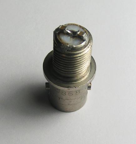
Figure 3 shows the measured magnitude of the impedance for the two 0.47 uF capacitors in parallel. The most obvious feature is the deep null at 5.0 MHz. This is the series resonance of each capacitor along with the series inductance of the small package. Roughly speaking, this puts the inductance at 2 nH. This is in good agreement with the inductance found from the reactance measurements made well above the series resonance. It should be noted that these measurements were made with the chips soldered directly to a UG-1094 BNC connector with the teflon and center pin cut back to the barrel (Figure 4). Use of these capacitors on a PC board would require ground vias that could increase the effective series inductance some.
A very easy method to roughly characterize the chip capacitors is to find the low frequency capacity from the straight line region on the left side of the plot, the series inductance from the right side straight line and the series resistance from impedance the bottom of the null. The least accurate of these three numbers is probably the resistance, which is very difficult to measure with a 50-Ohm system. Better accuracy comes from insertion-loss measurements made with two chips shunted across a 50-Ohm transmission line. In the case of the two 0.47 uF chip caps, the insertion loss is 73.6 dB corresponding to a series resistance, for each capacitor, of 0.011 Ohms. This null is of course at about 5 MHz. So now the simple series RLC model is 0.45uF, 2 nH and 0.011 Ohms.
More detailed models of the MLCC components are not generally needed. But the measured data showed a decrease in capacity from audio frequencies through the 100 KHz range, as is known for the high dielectric constant insulating materials. Additionally, the effective inductance above the hundreds of MHz decreases a small amount with increasing frequency. As was pointed out by IN3OTD this behavior is again expected [see note 7].
One to four of these 0.47 uF components can make a very effective RF bypass for the 0.5 to 500 MHz region, and with a bit of care can be applied at a wider frequency range.
Going to lower frequencies - Suppose that you need more effective bypassing at frequencies below 0.5 MHz, or so. The obvious solution is to use larger values of capacity. One concern is that this large C will increase the series inductance and thus reduce the performance at high RF frequencies. This is not the case, and in fact the opposite is true. Measurements were made on a single 1210 chip 100 uF. Figure 4 shows the result for two in parallel, created by halving the measured impedance for a single C. The graph shows that the impedance stays below 1-Ohm all the way from 1 kHz to 400 MHz. The noisy looking data around 1 MHz is exactly that. The impedance is difficult to measure, again. The insertion loss measurement put the series resistance at 0.0016 Ohms. At this point the simple series RLC model is 90uF, 0.9 nH and 0.0016 Ohms. This is outstanding broadband performance.
As of this 2017 writing, the factors keeping the 100 uF category of MLCC's from being a complete solution are voltage ratings and cost. Looking at Mouser and DigiKey, the highest voltage seems to be 16 Volts and the cost is in the US $2 range for small quantities down to about $1 in 100's. Additionally, if the frequency range of use is into microwave frequencies, one needs to be cautious of the effects of series inductance.
Performance of filters - Many bypass applications are trying to prevent interaction between a circuit, such as an amplifier, and the outside environment, such as a power supply. There are endless variation on this situation but they all come under the general category of filtering. Here we will just take a sample of a few filter circuits to get an idea of the performance of multiple MLCC components.
First, lets look at low power filter built from a parallel pair of our 0.47 uF chips and two ferrite beads, in series on each end, forming a 'T' circuit. Sticking to the 0805 package for the beads (historically, they were actual beads around wires, so we retain the term), one possibility is a Murata product, BLM21PG331SH1D. This is referred to as a 330-Ohm bead which is the rough impedance somewhere in the 200 MHz range. Murata rates this component for up to 1.5 Amps of current, so it is suitable for many circuits. Other 0805 beads are available with less inductance but higher current ratings.
We were able to think about the capacitors in simple terms of either an C, R or L, depending on the frequency. This is not the case for the ferrite bead. The graphs of Figure 5 shows the series resistance and reactance through the full frequency range. In general, the two components of impedance are commensurate in values and need to be considered together. This represents a lossy characteristic that tends to prevent big resonant peaks or dips, making for a wideband series element for our filter. It also suggests that both components of impedance be plotted separately, and thus the added graph.
Constructing the 'T' filter on a small piece of 0.063-inch thick PC board with coaxial connectors makes insertion loss measurements practical. Figure 6 is a plot of the resulting insertion loss. This is measured between a 50-Ohm generator and a 50-Ohm load. There is no particular reason to feel that this is the right choice of measuring impedance levels, but was used because it is common for commercial filters, and it is consistent with available network analysers. In addition, it is as reasonable a value as any other.
This is looking useful. At least 60 dB of insertion loss is achieved from 2.8 to 600 MHz, covering a large number of amateur bands. The amount of board space required is small and the part cost, even quantities like 10 is about 30 cents.
The next obvious step is to change the capacitors to the 100 uF type, keeping the beads. Figure 7 shows the resulting insertion loss.
Using the 100 uF capacitors produces an insertion loss of over 40 dB from 4 kHz to 2 GHz. The 60 dB range is from 45 kHz to 750 MHz. This sort of filtering performance allows excellent isolation of circuits, even when they are all built on the same PC board. It also is an excellent basis for taking DC and low frequency signals on and off of boards.
Measurement Methods - The frequency range being used here ranges from 10 Hz to 3 GHz. To get accurate measurements of resistance and reactance (impedance), three different instrument set ups were used. From 10 Hz to 40 KHz, a home-built DSP-based vector network analyzer (VNA) [note 4]. From 50 kHz to 60 MHz an N2PK VNA was used [note 5]. And, finally, from 60 MHz to 3 GHz an HP8714B VNA measured impedance using the built-in bridge. The data from the various instruments were transferred by files to the Gnumeric spread sheet program where a few calculations, such as magnitude of impedance, were made and the graphs plotted.
All of the VNA arrangements listed also have provision for measuring 50-Ohm insertion loss and were used. Again, Gnumeric did the plotting of the graphs.
While the component data were in the spread sheet, they were converted to scattering-parameter files suitable for linear circuit analysis [note 6]. This is useful for constructing power filters on the computer and exploring various configurations.
Conclusions and open questions - This note continues to support the case for the use of high capacity chip capacitors for bypass and filtering applications. Anywhere from 1 to about 4 such components can be paralleled to increase their effectiveness. The values can be chosen to suit the application, but should generally favor the high capacities.
As far as open questions, at VHF and higher frequencies, the series inductance of the chip caps is a limitation. Exploration of PC board layout schemes to minimize the added inductance could be useful. Some circuits only handle low amounts of DC current and here the ferrite beads can be replaced by resistors, reducing costs and improving performance. Multiple beads or resistors can be placed in series to improve the performance, taking advantage of the small chip size. These could be measured. There are difference in the circuit behavior of different ceramic materials, Z5V, X7R, etc. This includes changes with applied Voltage as well as temperature and should be investigated. One area of interesting study would be non-planar circuits that could mimic tubular feedthrough capacitors and their great performance at microwave frequencies. Along those lines is exploration of the construction of shielding to be used with the planar filters, such as discussed here.
High value MLCC - It has been six years since the information above was issued. During that time, the chip capacitor manufafturers have been busy increasing the capacitive density of the MLCC parts while, at the same time, lowering the purchase price. A recent look at Mouser and DigiKey listings showed some exciting improvements. A couple of examples are the C3216X5R1E476M160AC from TDK that is 47 uF and 25 Volts in a 1206 package. These cost $0.58 US in 100 quantity. At this writing, Mouser is showing just under a million of these in stock, suggesting that they are used in many products. A second, more amazing, example is Samsung's CL21A226MAYNNNE which is 22 uF at 25 Volts in the next size smaller 0805 package and costing only $0.097 in 100's at Mouser. The tiny package suggests good high frequency performance as we will explore while 22 uF is big enough to qualify it for many low-frequency bypass applications.
Characterizing these parts requires some careful measurements. The basic capacitor is easily measured, and using the Audio VNA, the Samsung MLCC was determined to have a low frequency capacity just under 22 uF. But the series inductance and resistance needs specialized measurements, as the values are below the the range of ordinary VNA measurements. A pair of the Samsung 22 uF MLCC's were shunted across a short length of 50-Ohm line on a PCB with good sized ground vias. VNA measuremnts of the 50-Ohm transmission loss showed the highest attenuation to be 86 dB at 1.64 MHz. For 44 uF total capacity, this is a series inductance of 0.21 nH or 0.42 nH per capacitor. The depth of the null indicates the series resistance, since the inductive and capacitive reactances have been cancelled out. This procedure is explained in section 7.9 of EMRFD (the first reference, below). Using the formula of Fig. 7.67, the series resistance at 1.64 MHz is 0.0013 Ohms, a remakably low value! I have access to a HP8714B VNA and used that to measure the insertion loss up to 2 GHz. No internal resonances were seen and the insertion loss at 1 GHz was about 28 dB, consistent with the 0.21 nH series inductance for two capacitors.
At this point it is worth comparing these ceramic components with chemical components such as aluminum electrolytics or tantalums. The ceramics are easy winners for low series inductance and resistance. Several 47 uF electrolytics and tantalums were studied in the a writeup of the Audio VNA (towards the bottom). These were seen to have series resistances around 0.1 Ohms. The series inductances are set by the sizes of the devices at values of several nH or more. Long term life of a ceramic device would seem to greatly exceed a chemical type. High voltage is the one area that favors electrolytic types. The higest voltage 22 uF MLCC are 100 Volts, such as TDK's C5750X7S2A226M280KB. But even in quantity, these are priced around $3.50 US. Electrolytic capacitors, such as Nichicon UVY2W220MHD with 22 uF and 450 Volts are priced around $1.00 US making them often the choice as voltage ratings go up.
The low series resistance of the MLCC can need special consideration for some applications. If connected across a very low source impedance, such as a large battery, the in-rush current can be very high. A series current limiting element may be needed. Also, some low-dropout voltage regulators may have minimum series resistance specifications for the output capacitors, to ensure stability. In all cases, it is important to consider the application and possible problems created by the low series strays. Also, remember that the temperature coefficients of these high value capacitor are quite high and the capacitors are often poor choices for timing or resonant circuits.
The little 0805 capacitors lend themselves to paralleling. This is less expensive than buying larger value capacitors. A few precautions are needed. First, it is important to keep the multiple components as close together as possible. With two parts, it is easy to have them located on each side of a power trace. This can also be done with four capacitors using 45 degree mountings, as done with a this filter board. Second, and very important, is to not parallel these caps with other values. The description of the problem was made at the top of this writeup. But, remember that these capacitors are already doing everything a bypass capacitor can do. Paralleling other values, with out series elements, can only degrade the performance.
The 22 uF, 25 Volt described above, as a general workhourse bypass and power filtering capacitor, is tough to beat. But, if one does not need the voltage rating, more capacity is possible without getting into expensive parts. For instance the Samsung CL31A107MQHNNWE is 100uF at 6.3 Volts in a 1206 package and as of February 2023 selling at Mouser for $0.185 US in 100's. Without spending too much more per micro Farad, there is the Murata GRM31CR60J227ME11L, 220 uF at 6.3 Volts in a 1206 package at $0.67 US in 100's.
Going to lower frequencies - We explored the use of MLCC commponents around 0.47 uF along with ferrite beads, above. Results could be excellent for the RF frequencies, above about 1 MHz. By using a pair of (expensive) 100 uF MLCC we extended the performance down below 1000 Hz. This is still not good enough for many applications. A mixture of sensitive analog circuitry with digital circuitry and microprocessors can end up with power line coupled noise signal. With the low cost 22 uF MLCC discussed above, it became worth while to explore better series elements than the ferrite beads. It became obvious there were three competing parameters, inductance, current capacity and physical size. As a start, it was decided to see what could be done for low power circuitry in the 100 to 500 mA power range and with a board area less than a 3/8-inch (9 mm) diameter circle. That was felt to encompass a wide range of applications in a size that would not be burdensome.
The graph above summarizes the filtering capabilities of the 150 uH and 1 mH inductors. This shows the magnitude of the complex impedance for the inductors and the 22 uF capacitor. This is all at frequencies 40 kHz and below. If a power-line filter is constructed by a series inductor followed by a shunt capacitor to ground, the filter is becoming effective at frequencies roughly above where the inductor and capacitor lines cross each other.
We are now ready to combine the inductors and capacitors into a power filter. The experimental one used here was built onto a connectorized PC Board for convenient measurement.
Comparing Figures 7 and 10 in the region below 1 MHz, it is seen that having 5 times the shunt capacity is slightly more effective than going from a 330 Ohm ferrite bead to the 1mH inductor. If one used four 47 UF in place of the two 100 uF of Figure 7 the cost would be reasonable and ferrite beads occupy less board space than the 1 mH inductors. Another possibility is to use four plus of the 47 uF and two of the 1 mH inductors (suggesting another experiment!)
Don't forget that the inductors have DC resistance. For instance, the 1 mH one that we have discussed has just under 2 Ohms. At 250 mA this results in about 0.5 Volts of drop. This may be important for some applications. Also, as the DC current increases, the non-linear B-H curve of the ferrite cores causes a decrease in inductance. Generally, the manufacturer's rated current takes this into acount, in some way. I have not measured this change for the inductors used here. If anyone does so, it would be good to add some data here.
Going further down in frequency - There will always be some low frequency where the LC types of power filtering lose their effectiveness. If this is problematic it calls for some combination for active filtering for the low end and LC filtering for the high end. The simple example is a 78L05 voltage regulator. These regulators may struggle with broad-band output noise. If so the LC filtering on the output side may be the total solution.
Side Note: Magnitude of Impedance - Throughout this note we have used "magnitude of impedance" to quantify the performance of power filter components. For these components, at any sine wave frequency, the current and voltage are not in phase and this is described by the complex impedance terms, resistance and reactance. If we are constructing a filter with a passband, such as a Butterworth low pass filter, the details of the complex impedance are very important. But, for power filters type of applications, the attenuation levels are typically 20 dB or more, often much more. For this, the series component currents are not strongly dependent on the details of the complex shunt element, but rather on the impedance magnitude. As an example, if the attenuation is about 20 dB, the change with shunt phase angle is only about 0.9 dB and this becomes less as the attenuation becomes greater. It may be obvious, but the magnitude of impedance is the square root of the sum of the resistance squared and reactance squared. It is always a positive number.
Notes:
Original issue: 24 November 2017; Last revised: 22 February 2023. - Copyright © Robert Larkin 2017, 2023