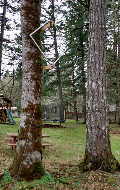
Description - We are located in a semi-rural area about 7 miles north of Corvallis Oregon. There is a small garden shed located 30-m (160 feet) behind the house that has electricity fed underground. This is where the KiwiSDR receiver is located. The antenna is a 1-meter-on-a-side square loop constructed out of PVC pipe with #10 wire fed through the PVC pipe. At the bottom of the loop, there is a transformer built with 4-turns bifilar-wound on a high-mu FB-73-2401 core. This gives balance to the antenna side and a 50-Ohm output feeding about 20-meters of RG-8/U going inside the building to a preamp and then to the KiwiSDR.
* UPDATE * It became apparent that for frequencies above 10 to 15 MHz, the loop was less than good. As an experiment to improve the 10 to 30 MHz range a dipole 5-m (16-ft) long and 10-m high was tried. Using WSPR tests, it showed considerable improvement for the 14, 21 and 28 MHz amateur bands. The downsides were too much sensitivity for the AM broadcast band and a increased pickup of local noise (household/digital) in the 5 to 30 MHz region. So, the next experiment was to add a diplexer with a cross-over frequency of 8.5 MHz. This diplexer has a 3-pole HP and 3-pole LP filter arranged to have low VSWR (<1.2) from DC to 30 MHz. This is showing promise as a way to use both antennas at the frequencies where they perform best. The 20-dB preamp is between the diplexer and the receiver, and so is used with both antennas. 10 May 2020.
The preamp was found in the junk box and consists of two stages of wideband feedback amplifiers. These give about 21 dB of gain from 300 kHz to more than 500 MHz. The noise figure is around 5 dB and the output power capability is around 13 dBm. Nothing is balanced after the transformer, but fortunately there are no local AM stations and 2nd order intermodulation has not been a problem. The transformer presents a balanced load at the lower frequencies and makes the unshielded loop non-responsive to electrical fields. The preamp is located indoors, but the loss in the cable is not very large. The impedance seen by the inductive source impedance at the antenna is close to 50-Ohms resistive with or without the cable in between.
The KiwiSDR is mounted on a metal plate that is treated as "ground." The RF and GPS antenna connectors on the Kiwi are bonded to the plate. So is the Ethernet connector shell, along with that end of the board.
For now, and maybe forever, the GPS antenna is on a steel plate sitting under the roof of the shed. GPS reception is adequate with this position of the antenna and it is out of the weather.
My experience in making W7PUA KiwiSDR available on the Internet - My particular Internet situation is that we own the domain name "janbob.com" but it is hosted, along with many others, at HostGator.com. This means that our IP address can change at any time. It is found by a DNS lookup (for instance at this writing it is 108.179.234.130), as was set by HostGator. Additionally, the local IP address is set by our router and can be either static (fixed)) or dynamic (can be changed by the router). The various methods for dealing with these issues are covered by the KiwiSDR Guide and repeating that information here is unnecessary. I will only show the details that worked for me with my situation. If you situation is like mine, this may help you get things going. Here are a couple of links to summaries of the setups that worked to make the KiwiSDR data available on the Internet:
When first connected, there were two problems. The audio would drop out several times per minute.
This was traced to the poor Wifi percormance over the 50-m path from the KiwiSDR to the
router including going through a wall of the house. This was easily solved by using a home-brew
12-element 2440 MHz Yagi antenna, thereby increasing the signal level. More difficult to solve was the strong
collection of signals from the Ethernet cable between the KiwiSDR and the
Vonets VAG11n-300 Ethernet-to-Wifi Adapter. This is described next.
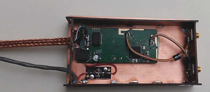
Ethernet Noise - The interference in the 15 to 30 MHz region went away when the antenna was disconnected from the preamp. This was painting a picture of "stuff" being radiated from the Ethernet cable and the Vonets Wifi Converter and being picked up by the loop. I built a box out of PC board material that completely enclosed the Vonets board. The PCB Wifi antennas were disconnected with Exacto knife cuts and SMA coax connectors replaced the antennas to be used externally. A power filter, consisting of two "330 Ohm" ferrite beads and two 0.47uF chip caps, was placed on the 12-V line and a shield, made from RG-8/U cable braid, covered the existing Ethernet cable that came with the Vonets board. A wire was added at the KiwiSDR end of the braid to ensure a good ground connection there. Not shown here is the PC board cover to make a full 6-sided shield.
Note that the cable that came with the Vonets adapter was completely unshielded. This is the case for much Ethernet cable. However, some CAT 7 cable comes with shielding on the individual twisted pairs as well as on the entire group of four pairs. This would seem like an excellent choice for use around any radio system. Be sure that grounds are connected at the connectors. If the cable is long or AC power is derived from different sources, there may be issues of "ground loop" currents on the shield. This is out of the scope of this discussion, but may be an issue. The individual Ethernet twisted pairs are always terminated in isolation transformers to prevent ground loop problems for the data.
The good news is that the interference went away as viewed on a full 0 to 30 MHz spectral sweep. A few interfering sgnals remained on narrow sweeps, but these were weak enough to be barely audible. Comparison of this screen shot with the one before the Ethernet shielding reveals that there was more interference than just the obvious big stuff between 15 and 30 MHz. For instance, the whole region between about 2 and 7 MHz has dropped by several dB. The color of the waterfall provides an easy way to see the changes, as all waterfall settings are the same between the two screens shots and the antenna and preamp are unchanged.
Ethernet interference Measurement Hints - While pursuing the reduction of noise from the Ethernet system I found that I always had a pair of signals at about 20257 kHz. They were among the stronger signals, and looking at other KiwiSDR setups with Ethernet interference, they seem to be near the same frequencies. In addition to observing these via the KiwiSDR interface (20259kHz LSB), I would tune my Yaesu VX-7R hand-held radio to 20260 kHz AM. Using the standard rubber ducky antenna as a probe, it was easy to evaluate the relative strengths of these signals. The fact that there are a pair of signals makes them very audible in the AM mode.
Noise Level Measurements - The figure above, with four spectrum plots, shows the noise levels that were seen by observing the KiwiSDR screen with the "Spec" running. Starting with the bottom "D" plot it is seen that the KiwiSDR noise level, for the FFT bandwidth of the full 0-30MHz sweep, is just above -110 dB, with 2 or 3 dB more near 30 MHz. Next, the "C" plot shows the increase in noise level with the addition of the 20 dB preamp. This increases the noise by 6 or 7 dB across the band, showing that about 75 or 80 percent of the noise power is now coming from the preamp. As a starting point, this looks good. Jumping to the top "A" spectrum we see the result of replacing the 50-Ohm termination with the 1-meter loop antenna.The major point of comparing the "A" and "C" spectrums is that for frequencies below 15 or 20 MHz, the external noise exceeds that of the preamp by another 6 or 7 dB. This noise is coming from the antenna and we want it to be the dominant noise power. Again this is in the general range that we desire.
An aside is that this "A" measurement was made in late afternoon on a winter day. Thunder storms were far away and few. Additionally, in the region of a few MHz the D-layer of the ionosphere was preventing atmospheric noise from being propagated by the F-layer. These two factors made the noise on the left side about as low as would be observed. Similar measurements made at night show an increase of around 3 dB in the 2 to 5 MHz region. Because of low sun-spot levels, the noise in the 7 to 15 MHz region drops at night, however.
All of the work described above was done with the Ethernet running with a 100 MBit/sec setting. I recently read that running at 10 MBit/sec could reduce RF spurs. I tested this with the described shielding and filtering in place and could not see any difference. The Vonets adaptor only uses a 4-wire interface and may not ever run at 100MBit/sec, I don't know. It is worth trying, of course, and is set from the KiwiSDR administrative page under the "Network" tab.
Comments, corrections, bright ideas and questions are welcome. Send to bob, the 'at' sign followed by janbob dot com. Thanks, Bob W7PUA
Issued 1 Jan 2020. - All Copyright © Robert Larkin 2020