Why?? This is a simple piece of test gear that produces a known amount of Gaussian random noise at radio frequencies. This is connected to the antenna input of a radio receiver and the receiver output noise level is estimated or measured with this Noise Generator both off and on. This change in output noise can by itself be an indicator of the working state of the receiver. But, in addition by applying a bit of algebra to the noise difference, we can measure the Noise Figure of the receiver this noise to the input of a radio receiver, the amount of noise coming from the receiver can be estimated.
At all radio frequencies below about a GHz, the noise spectrum is quite flat, causing the noise to appear as "white" noise. The performance above 1 GHz needs further exploration.
The basic circuit used here is not at all new. An excellent starting point for seeing the method in more detail is the excellent Paul Wade, W1GHZ, article from November 1996 QEX, Noise Measurement and Generation.
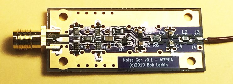
Construction - All components mount on the top of the 1.83 x 0.79 inch, 1/32-inch thick PC board. The markings on the board show where the components are placed, except for R2 that is above R1, R4 that is above R and R5 that is just above Q1. The one SMA connector is an edge connector that is pushed tight against the board and soldered first to the top sided of the board. The common connectors of this type have a 1/16-inch gap for the board. I found that the leads from a quarter-Watt resistor are the right thickness to fill the ground gap on the back of the board. A pair of these leads do the job with one of them against the connector body
Many of the surface-mounted-component PC board pads have a grounding system that involves two or three plated-through holes. In order to lower the series inductance of the ground path, there is no thermal relief for these holes. To ensure getting a good solder connection, be sure to heat these pads with the soldering hot enough to make the solder flow.
The transistor is in a tiny SOT343 package. This has four pins, and the pin that is wider than the rest goes to the ground pad by the letter "Q" in "Q1."
Shielding and filtering is very important. We do not want the Noise Generator to be acting as an antenna. The noise level we are working with is very low and any interfering signals, like FM, TV, Cellular or your room lights will defeat the measurements. The power lead has proven power filtering. The shielding is not shown here, but the open copper (no solder mask) along the sides of the circuitry allow a tinned-metal cover to be added. This can be made from thin metal, either tinned or brass such as is carried in hobby stores, and formed to a squared 'U' shape over something about 0.375 (3/8-inch) wide by 0.187 (3/16-inch) high. The length of the shield is about 1.6 inches and the power end is open. The RF end of the shield should be soldered to the SMA body. There are small gaps on the RF end that should not be a major problem. [Added 25 Jan 2019]
Part List
PC Board    OSH Park shared project-see below*
C1          0.01 uF, 16 Volt or more, 0805
C2 to C4    0.47 uF, 16 Volt or more, 0805
J1          SMA edge mount for 1/16 or 1/32-inch PCB
L1          "330 Ohm" ferrite bead, 0805, Mouser 81-BLM21PG331SH1D
Q1          Infineon BFP620 H7764 Mouser 726-BFP620H7764   [Corrected part # 25 Jan 2019]
R1, R2, R4, R5  200 Ohm 5% 1206
R3          68 Ohm 5% 1206
R6          1K Ohm Ohm 5% 0805 (revised 17 Jan from 330))
R7          470 Ohm 5% 0805
*This is the "shared PCB" link. Three boards are available from OSH Park for $7.15 including US shipping. Be sure to order these with the "2 oz copper, 0.8 mm thickness" option, selected at checkout. Note this option is not selected unless there is a check mark in the box next to it.
Theory of Operation - Zener diodes are known to be noisy. Most zener diodes have enough parallel capacity and lead inductance to limit their use to lower frequencies. Bipolar transistors made with the Si-Ge process can now achieve transition frequencies up to around 60 or 80 GHz. To achieve this microwave performance suggests that both capacitance and lead inductance are small, opening the possibility of using these for noise diodes. The zener action occurs when either of the junctions is reverse biased to the point where reverse current flows. This project explores the use of the base-emitter junction as a zener diode noise source.
I choose the Infineon BFP620 device in a SOT-343 package for this noise source. The ft is around 60 GHz suggesting that it would work in the microwave range. The package is small but can be soldered with a fine tip soldering iron and some magnification. There are other similar devices available from several manufacturers, but this is the only one I have tried, so far.
The other parameter that needs to be determined is the operating current. The forward conduction base current is spec'ed at 3 mA max. It is not clear how this relates to reverse current that is not specified. I have used values up to about 10 mA, and so far have not burned out the junction! More current produces more noise, but at this point, I am suggesting a current in the 5 to 6 mA range. This needs more experimentation. The zener voltage of the BFP620 is around 4.5 Volts. [REVISED 17 Jan2019 I had a failure of Q1 while doing measuremnts at 5.5 mA. I do not see any clues as to the cause being due to outside forces. For now, I have backed off to 3 mA that is achieved with R6 = 1K Ohm.
The change in noise output with DC current requires voltage regulation for using this noise source as a "lab instrument." The resistor values shown are for a -9 Volt DC input, producing about 5.5 mA of current. This arrangement is very suitable for running from a 9 Volt battery, producing a little test device that can be used for quick verification of receiver performance. Of course, a regulated 9 Volt source can be used as well to better control the noise output. Note that it is a negative voltage, relative to ground.
The RF impedance of the diode changes from DC current on to DC current off. This can change the gain of the amplifier being tested. To minimize this effect, a resistive attenuator (R1 to R5) is placed between the noise diode and the output connector. Nominally, the attenuation is 10 dB with some effects from stray capacity and inductance at microwave frequencies.
Measured Performance - The Excess Noise Ratio (ENR) is standard measure of noise output from an RF noise generator and is defined as 10 * Log10((Th - 290) / 290) in dB. Th is the effective noise temperature of the source in Kelvins. I did a number of direct measurements of ENR using frequency converters ahead of a DSP-10. These demonstrated that there was noise, and gave the ENR at a few frequencies. I was testing at currents up to 8 mA, and as expected the noise output increased with higher current.
After many hours of testing at 6.5 mA, Q1 failed. I replaced Q1 and changed R6 to 1K Ohm, corresponding to 3 mA of current and now called sample "1A". This rebuilt sample has run for a few hours without problems. In addition, I repaired the power supply in my old Eaton 2075 automatic noise meter, bringing it back to full operation. This is convenient as it can be calibrated for any sweep of frequencies from 10 to 1800 MHz using a known ENR noise head, and then the ENR can be read directly for an unknown head (noise generator). Using this method I ran a curve of ENR from 100 to 1800 MHz in 100 MHz steps, as shown below. The increase in ENR at 90 to 110 MHz is clearly the result of local FM stations, and those points should be ignored as is indicated by the dashed line in that area. The Noise Generator was being operated without the shield, and that is likely contributing to the RF pickup.
.So, other than the QRM qualifiers, this curve is representative of what the noise generator will
do, using the BFP620. Here is the curve:
An interesting characteristic of this noise generator is the increase in ENR below 100 MHz. Rick, KK7B recognized the shape as 1/f noise, and his explanation very much fits the data. We usually think of 1/f noise as a trait of devices at low frequencies, such as 10 KHz or less. The minute size of the 65 GHz BFP620 has apparently scaled the frequency of 1/f noise up considerably. The measurements have been checked in several ways, including against a Sylvania 5722 vacuum tube noise diodes and the results are consistent. It does not change the usefulness of the generator as long as the higher ENR is taken into account.
The impedance match was measured up to 3 GHz. The match itself could use some work,
but the change in impedance between on and off is minimal. The following show just the
magnitude of the reflection in terms of return loss.
Using the Noise Generator - A very effective way of using the generator is to connect it to a radio receiver and turn it on and off. Experience will show what to expect and faulty receiver operation will be apparent. This may be done by watching an s-meter. In some cases it is beneficial to listen to the audio output, in which case turning off any AGC will be good. For some radios, this can be accomplished by lowering the RF Gain while increasing the AF Gain.
To quantify the measurement, we turn to Noise Figure. This measure of receiver sensitivity requires a pair of noise power measurements, one with the generator on, and one with it off. This can be done using an AC voltmeter connected to the audio output with the AGC off. If the ratio of these two measurements is the variable y (a power ratio, not dB), then the noise figure is NF = 10 * Log10(enr / (y-1)) dB where enr is a power ratio also, given by enr = 10 ^ (ENR/10). This measurement has a number of subtleties that can limit the accuracy, but obtaining answers to a fraction of a dB is quite practical in a home lab.
If the measurements being made are of low values of NF, say up to 5 dB, it is desirable to include an additional 5 to 10 dB attenuator in cascade with the generator output. This improves the VSWR, reduces the bit of change in VSWR between the on and off states, and reduces the errors in the measurement. This attenuator should be of low VSWR.
Background information on the NF measurements:
Issued 15 Jan 2019 - All Copyright © Robert Larkin 2019 Revised 17 Jan to lower Q1 current to 3 mA.