We are going to explore several analog-to-digital converters (ADC) that are supported by the Teensy OpenAudio_ArduinoLibrary for floating-point DSP. Eventually, this will be expanded to cover digital-to-analog converters (DAC) which are often packaged with the ADC as "CODEC's." But, at first the purpose of this study is to find an ADC for use with the Audio Vector Network Analyzer project that does not have the common flaw of "idle tones."
NXP's SGTL5000 - By far, the most popular conversion product used with the Teensy 3.x and 4.x processors is the NXP SGTL5000 CODEC. This has been offered by PJRC as their Teensy Audio Adapter. This is good as it is available only in the very small QFN-20 package and unsuitable for hand soldering. For this study I plugged this adapter to a Teensy 4.0 and evaluated the performance in several ways. The two graphs, just below, show some of the results. The dark blue graph is the spectrum of the digital signal with a resistor connected across the input and no signal connection. It can be seen that there is a somewhat noisy, and yet coherent signal at about 1500 Hz, hitting a level of about -92 dB below full ADC input (full scale, or FS). More of these signals can be seen at roughly the odd harmonics of the base tone. The "true" noise level is down around -114 dBFS, measured in a 44100/1024=43 Hz bandwidth. This artefact of some ADC's is called an "idle tone," and is well known by the Sigma-Delta converter experts, but not widely touted in the spec sheets. Two interesting characteristics of the idle tones are that their amplitude and frequency depend on the level of incoming signals and that they occur only in certain design topologies of the converters.
The lower time series graph shows the strange noisy square wave that the idle tone produces. The long term ups and downs are DC shifts that are also part of this class of converters.
The SGTL-5000 includes an input amplifier that can provide up to 22 dB of Line Input gain. The tests here were done at the lowest gain setting. At the highest, one could just start to see the increase in bottom level noise. I did not include any data with the higher gain as the differences were so small.
I next applied a sine-wave input to the SGTL5000 converter. I chose 2756.25 Hz as it was the 16th sub-multiple of the sampling frequency and also was in an area without idle-tone energy. Since no FFT window was used, it was important that the sub-multiple be exactly the 16th sub-multiple. The HP33120 function generator that generated the test sine wave uses a crystal oscillator reference to be close to the correct frequency. But this needed to be iteratively adjusted, very slowly, to minimize the spectral leakage. This ended up showing 2756.2765 Hz on the panel. The first test was at an amplitude 60 dB below ADC full scale and the FFT spectral output is the green curve. This response at 2756 Hz is as expected. Interestingly, the idle tones are not gone, but have been shifted in frequency and amplitude. The base noise between idle tones is essentially the same level as was seen with no input. For the next measurement, the level was raised to 1 dB below full scale. Harmonics can be seen, with the strongest being the The signal from the function generator that could be the source of the harmonics that are seen. I do not have an analog filter to allow a really clean sine wave to be applied, so we don't know the level of distortion in the ADC. We do know that this class of ADC are inherently very low distortion.
TI's PCM1808 - This device is only half of a CODEC doing the Left and Right ADC function. It is simple to apply as it has no control functions. The output data is in an L-R pair of I2S 24-bit words. The package is a TSSOP-14 that for many is hand solderable. The same tests were run on this device as above. Similar spectral and time series graphs are shown below. The obvious difference is the lack of idle tones. This makes it possible to use a single number to describe the noise in the mid-range of frequencies. This is seen to be about -120 dBFS in the 43 Hz bandwidth of the FFT. That can be seen in the lower time-domain graph which is shown in LSB units for 16-bits. The general character of this is random uncorrelated noise. The standard deviation of the time data is 0.6 of these LSB units. The time series graph just shows 100 points, as the process is stationary (unlike the SGTL5000) and the next 100 points looks about the same. Observe, though that you are able to see the benefits of 24-bit output by examining the data points between the 16-bit LSB levels.
When the -60 dBFS signal is applied, the only change is the addition of the single spectral spike. When the signal level was raised to -1 dBFS, many pseudo-noise like artifacts appear at a level around -115 dBFS. This did not occur with the SGTL5000 and suggests that the "big signal" capability of the PCM1808 has some minor issues. The test tone is 2756.25 Hz and harmonics are producing responses at -74 dBFS or lower. As before, the source of the harmonics could be either the function generator or the ADC. Just ignore these harmonic responses, or devise an experiment with LC filters to remove them from the source.
A detail in using the PWM1808 is that its minimal control is provided by a few hardware pins, and there is no software driven I2C or SPI control. The I2S data needs to be on the right hardware pins, but I2S data has no identification. Thus, for simple testing, the Teensy Audio system works fine by envoking almost any CODEC and certainly the SGTL5000. If it is being used by itself in a system, it would be good practice to not have stray software control.
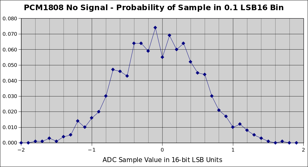
Revisiting the time series, a random sample of 1000 points was taken, with no signal input. A histogram of the values was taken and is shown below. In order to not include the DC level shifts, the data was run through an D=16 running-average high-pass filter. Next a series of 1000 points was analyzed to form a histogram, shown below. This is a good time to note that, in some form, the output of the PCM1808 must be high pass filtered. The "DC" excursions at frequencies below a few Hz are quite large.
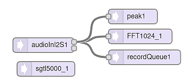
Miscellaneous comments. The method of measurement was simple and shown in the flow diagram, below. This all operates with a Teensy 4.0 processor using the F32 DSP library. The DSP classes were brought in by the Design Tool. Operation simply ran the ADC with time series data coming from the recordQueue class and the Fourier transformed data from the recordQueue_1. The peak1 class allows one to see how close the input is to overloading the ADC.
The I2S output of the SGTL5000 is L-R 16-bit words. For the PWM1808 this is the same but 24-bits. I2S format deals with any word size up to 32-bits by going until there is no more data. But, be careful. There is a subtlety in that the Teensy Integer I16 input of I2S audio truncates the output to 16-bits. The F32 audio library handles any word length up to 32 bits, including 24 from the PWM1808. If you input the the Codec data as I16 and then convert it to F32 with the convert_I16toF32 class, 8 bits of resolution is lost. Looking at the time series for the PWM1808 shows this to be significant.
A few thoughts on what is important. If we are processing audio to be later heard by the human ear, the dynamic range of the ear becomes a factor. Fletcher-Munson types of curves tell us that if we are playing sound at a very high level, we would marginally be able to hear the idle tones of the SGTL5000 when we stop the loud material. This is probably not going to bother anyone. On the other hand, if we are using the same ADC with a radio receiver, the range between a strong signal (-20 to 0 dBm or more) and a weak, but useable signal (say -140 dBm) shows the idle tone to be a big dominant factor. We will never have too much dynamic range. Instrumentation applications, such as the Audio Vector Network Analyzer. have the same problem, but with the ability to sometimes move idle tone frequencies by changing sample rates. But, having the tone-free spectrum and lower noise, such as the PCM1808 offers, will end up with better performance.
Update - Power Supply Filtering - [Added 8 May 2025] Some good questions came up during discussion with the T41 transceiver group. This prompted me to make more measurements with the intent of finding out how much power filtering on the analog supply was required. Backing up a bit, the SGTL5000 measurements were made with a standard PJRC audio adaptor, plugged into a Teensy 4.0. The results above show that the ADC noise is covered by idle tones. In the frequency domain, this is not fully true, as the idle tones are, more-or-less at specific frequencies. But it still didn't seem to be useful to spend much effort reducing the ADC random noise.
Since the PCM1808 ADC has no idle tones, it seemed to be a useful target for experimentally reducing the ADC noise. The data that was taken taken above used an ebay PCM1808 breakout PCB that includes pairs of 10 uF electrolytics along with parallel 0.1 uF ceramic chips. This is very close to the suggested filtering in the TI data sheet. My test configuration had one major addition and that was a 10 mH inductor between the 5.0 Volt Teensy pin and the 5 Volt Vcc input to the 1808 board. I have used the 10 mH filter inductor in several projects and it seemed beneficial, as was later confirmed. To quantify the effect of this filter component, the no-signal ADC noise was measured for three cases, (1) No series L, (2) a 10 mH series L, and (3) a 1 mH series L. The raw data is a set of 512 ADC noise powers corresponding to the frequency bins of the 1024 point FFT. The data is presented as differences in dB between the "no series L" case and the two inductor cases, as this makes the results most obvious. To provide a reference for these difference curves, the blue, no-signal, curve of Figure 2 is the 10 mH series L curve. The following graph shows the two difference curves, with lower points being more improvement.
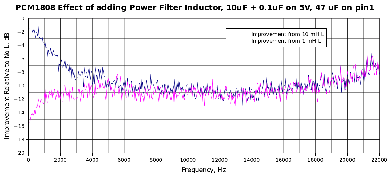
It would appear that noise on the 5-Volt line is appearing in the ADC output. Either the 1 or 10 mH inductors provides about 10 dB of improvement at frequencies above about 5kHz. This is substantial and well worth the investment of an inductor. Below 5 kHz, it gets interesting. I ran the 10 mH curve first and was not surprised that the inductor seemed less effective at lower frequencies. When the 1 mH inductor was substituted, I anticipated an in-between result. That is not the case at all. The smaller inductor is more effective! This clearly needs more exploration. Note that the 5-Volt bypass on the ebay 1808 PCB is that recommended by TI, a parallel 10 uF electrolytic and a 0.1 uF ceramic chip. Following the lead offtp.janbob.com the ceramic capacitor bypass study, it would be worth trying 1 or 2 of large value ceramic chips, such as 22 uF, 47 uF or even 100 uF. This probably will change the effectiveness of the series filter inductor.
Another important bypass capacitor is that on the reference voltage. For the PCM1808 this is pin 1. This reference voltage is generated internally and used internally for scaling of the measured voltage. All of the Figure 2, 3 and 5 curves were measured with a 47 uF ceramic chip capacitor on pin 1. This was selected after measuring ADC noise with a 0.1 uF, a 10 uF electrolytic plus the 0.1 uF ceramic, and a 47 uF ceramic. The latter two cases were substantially better than the 0.1 uF and it appeared that something like the 47 uF was a good all around solution, as well as being much smaller in size than an electrolytic.
Thank you Greg, KF5N, for helping me to understand the workings of these devices.
Issued 28 April, 2025. Revised 8 May 2025. All Copyright © Robert Larkin 2025.