The Audio Vector Network Analyzer (AVNA) uses a matched pair of differential amplifiers to measure impedance. One of these, called the Reference Channel, is connected at the drive source and always presents a minor load to that source. The Measurement channel, however, is connected across the impedance measurement connections and loads that voltage down. This is dealt with in the AVNA software by calculating the amount of loading and subtracting this. This process is call de-embedding and requires a circuit model of the differential amplifier input. In addition, there are wires connecting from the amplifier input to the measurement terminals. These wires appear as resistance and inductance in series with the device being measured. This stray impedance is also removed in the software. This note shows methods for measuring all the values that need de-embedding.
The amplifiers each have a 1 Megohm resistor across their inputs. This serves to speed up transient events when the circuits are changed in any way. Also, these resistors also are much smaller than the intrinsic input impedance of the MOSFET op amp and thus the Megohm presents a well defined load that is easily de-embedded. The input to the amplifier is thus 1 MegOhm in parallel with a capacity that is a few 10's of pF. One minor additional detail is a 0.22uF DC-blocking capacitor that is in series with the amplifier input.
So, one purpose of the tuneup procedure is to estimate the component values of the series R, the series L, the shunt capacity and the precise value of the 5% 1-Megohm resistor. In addition, it is sometimes possible to have very precise external resistor values that can be used to adjust the assumed values for the 50 and 5000 OH Rz values for the two internal Reference resistors.
This tuneup procedure is built into the AVNA software. The accuracy was greatly improved starting with version 0.61. Earlier versions should not be used for TUNEUP. TUNEUP requires multiple commands, as the different test conditions need manual component connections at the Impedance terminals on the panel. All TUNEUP measurements are run via the serial data link from the AVNA, using a PC/Laptop with the Arduino IDE. There is no interaction with the AVNA touch screen. The serial command, TUNEUP, with no following number will print a summary of the procedure. This can be used anytime and is a quick reference. The story here is more detailed and probably most useful the first time through. In that regard, this tuneup is not needed often. Probably for many it will only be used once at the initial testing of the AVNA. It would be used again if, say, the arrangement of the wires to the impedance terminals were re-routed.
Note that original TUNEUP procedure. remains as a valid alternative procedure to what is on this page. That procedure was based on knowing the 50 and 5K reference resistors and deducing the other values by trial and errror. It remains to be seen as to which procedure is best for a particular circumstance, and by use of the PARAM1 and PARAM2 commands, the two alternatives can be mixed.
Full example - For use here, there are four measurement commands, TUNEUP 1,2,3,and 4. Then TUNEUP 5 and 6 either save or discard the results. Here is a sample of a tuneup run I did. First, I entered the commands
PARAM1
PARAM2
TUNEUP
to get the current component values and the TUNEUP instructions onto the serial monitor window. You can always scroll up to see these. Next, to be sure of not having long printouts of technical details, be sure the VERBOSE is off (the default) with
VERBOSE 0Now, the first measurement takes place with a short across the Z terminals. I used a 1/4-W resistor lead, as it was handy. This will have about 15 nH inductance that is probably not worth dealing with. The measurement command is
TUNEUP 1This measures at two frequencies and takes some time with lots of averaging. The progress and results are printed as available, ending with, in my case,
Short should be connected across Z terminals.  Repeat TUNEUP 1 if not shorted now.
Doing short circuit tests...CAL 500 Hz...WAIT...
500 Hz Measurement/Reference Voltage gain = 1.0005764
500 Hz Measurement - Reference Phase (deg) = 0.000
Doing short circuit test...MEASURE 500 Hz...WAIT...
500 Hz  Rs = 0.004090   <----
Doing short circuit tests...CAL 40 KHz...WAIT...
40 KHz Measurement/Reference Voltage gain = 1.0000181
40 KHz Measurement - Reference Phase (deg) = 0.748
Doing short circuit test...MEASURE 40KHz...WAIT...
40 KHz  Ls = -167.4 nH   <----
TUNEUP 1 Short Circuit tests COMPLETE
Ready for known 50 Ohm test, TUNEUP 2 R50
The two important answers have arrows pointing to them. The rest of the data we can ignore for now, and in fact, the two important answers are being saved in the program, as well.
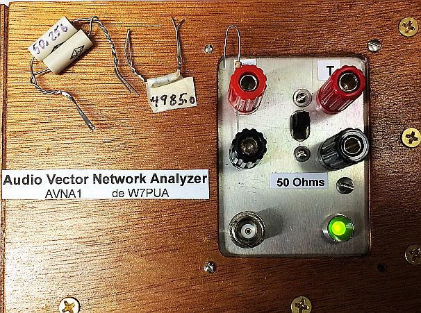
Next we connect a resistor that is roughly 50-Ohms to measure the internal 50-Ohm reference. The exact value is not important, but we need the DC value to be as accurate as possible. If you can find somebody with a calibrated 0.1% DVM, or better, get the owner to measure some of your your resistors. Make the temperature as consistent as possible during the various measurements, as the resistance varies. The measurement command includes the exact value, 50.256 Ohms:
TUNEUP 2 50.256The results are all at the bottom of this web page, so we won't repeat them here. This continues next to a check of the 5000-Ohm reference:
TUNEUP 3 4985.0and then the shunting 1-Megohm and shunt capacity are checked with the Z terminals open:
TUNEUP 4At this point, all measurements are complete and we will make them permanent with:
TUNEUP 5We could have cancelled the entire set of measurements with TUNEUP 6.
At this point it is best to do some swept measurements, perhaps using this same set of measurement conditions. See if the results seem reasonable. At 10 KHz or higher using a 5000 Ohm reference, the open circuit impedance should be many megohms, along with a capacity of a pF or less. Note that the the mathematics of impedance combined with noise in measurements causes switches in sign. For instance, 40 Megohms with noise might appear as -50 Megohms. Likewise 0.5 pF plus noise might produce a result of 4 Hy inductance. Connecting a 10 Megohm resistor to the terminal (or a 1 pF capacitor) should demonstrate the correctness of the answers. Similarly, testing a short ofr various resistors or capacitors should confirm that the TUNEUP was a success.
Comments - A couple of comments on the results may be helpful. First, the internal series inductance, Ls, measured at 40 KHz with a short connected, has consistently been around -170 nH. When I first saw this, I assumed a sign was wrong in the equations. If this is the case, I have not found it. Good, consistent, measurements come from this negative inductance value. When measured at lower frequencies, the inductance eventually switches sign, but the accuracy is poor since the reactance is extremely small at, say, 500 Hz. Maybe somebody can explain the negative Ls?
A second note is that, some of the time, the measured phase difference between the Reference and the Measurement channels will be -1.80 degrees, as:
TUNEUP 4
Measuring Open Circuit (1 Meg)...CAL 500 Hz...WAIT...
500 Hz Measurement/Reference Voltage gain = 1.0008765
500 Hz Measurement - Reference Phase (deg) = -1.801
This is the result of the SGTL5000 CODEC startup that sometimes shifts the left versus right ADC channels by one sample. The AVNA assumes there may be some phase difference between the two channels and subtracts out the difference, including 360 degree wrap-around, if needed. So the one-sample phase shift does not change the final impedance (or transmission) measurement values. Just ignore it.
Also, remember that any of the measured TUNEUP component values can be manually changed with the PARAM1 and PARAM2 commands. For instance, if you are annoyed at seeing open circuits as big inductors, a slight change in Cin will fix it. If you end up with say, 1 pF with no connection, it is easy to mentally subtract that value when measuring capacitors.
Sample serial monitor printout - What follows is a copy of all the serial monitor information for a full set of TUNEUP measurements.
TUNEUP 1
Short should be connected across Z terminals.  Repeat TUNEUP 1 if not shorted now.
Doing short circuit tests...CAL 500 Hz...WAIT...
500 Hz Measurement/Reference Voltage gain = 1.0005764
500 Hz Measurement - Reference Phase (deg) = 0.000
Doing short circuit test...MEASURE 500 Hz...WAIT...
500 Hz  Rs = 0.004090   <----
Doing short circuit tests...CAL 40 KHz...WAIT...
40 KHz Measurement/Reference Voltage gain = 1.0000181
40 KHz Measurement - Reference Phase (deg) = 0.748
Doing short circuit test...MEASURE 40KHz...WAIT...
40 KHz  Ls = -167.4 nH   <----
TUNEUP 1 Short Circuit tests COMPLETE
Ready for known 50 Ohm test, TUNEUP 2 R50

TUNEUP 2 50.256
rPrecise = 50.256
Measuring "50 Ohm" precision resistor...CAL 500 Hz...WAIT...
500 Hz Measurement/Reference Voltage gain = 1.0010089
500 Hz Measurement - Reference Phase (deg) = -0.000
Measuring precision 50-Ohm resistor...MEASURE 500 Hz...WAIT...
500 Hz: Measured internal 50 Ohm Ref Res = 50.301 <---
TUNEUP 2, Precise 50-Ohm, tests COMPLETE
Ready for known 5K Ohm test, TUNEUP 3 R5K

TUNEUP 3 4985
rPrecise = 4985.00
Measuring "5000 Ohm" precision resistor...CAL 500 Hz...WAIT...
500 Hz Measurement/Reference Voltage gain = 1.0010802
500 Hz Measurement - Reference Phase (deg) = -0.001
Measuring precision 5000-Ohm resistor...MEASURE 500 Hz...WAIT...
500 Hz: Measured internal 5 KOhm Ref Res = 5009.1 <---
TUNEUP 3, Precise 5K-Ohm, tests COMPLETE
Ready for Open Circuit tests, TUNEUP 4

TUNEUP 4
Measuring Open Circuit (1 Meg)...CAL 500 Hz...WAIT...
500 Hz Measurement/Reference Voltage gain = 1.0011256
500 Hz Measurement - Reference Phase (deg) = 0.000
Measuring Open Circuit (1 Meg and Cin)...MEASURE 500 Hz...WAIT...
At 500 Hz, Measured R1Meg, using R5K value of 5009.100 = 989646.5 <---
Measuring Open Circuit (Cin)...CAL 40 KHz...WAIT...
40 KHz Measurement/Reference Voltage gain = 1.0005534
40 KHz Measurement - Reference Phase (deg) = 0.739
Measuring Open Circuit (Cin)...MEASURE 40 KHz...WAIT...
At 40 KHz, Measured Cin, using R5K value of 5009.100, = 42.6 pF  <---
     Before TUNEUP, value was: 42.7
TUNEUP 4, Open Circuit, tests complete
------------------------------------------------------------------
Summary, the other 5 values:
   Rs = 0.0041        Before TUNEUP, value was: 0.0035
   Ls = -167.4        Before TUNEUP, value was: -171.4
   R50 = 50.301       Before TUNEUP, value was: 50.327
   R5K = 5009.1       Before TUNEUP, value was: 5011.1
   R1Meg = 989647     Before TUNEUP, value was: 992388
Ready for Save or Cancel, TUNEUP 5 or TUNEUP 6

TUNEUP 5
Making measurements permanent. Use PARAM1 or PARAM2 to alter these.
Issued 30 October, 2018. - All Copyright © Robert Larkin 2018