Birdwatcher-2 Building the Frames
Birdwatcher-2 Sailboat, designed by Phil Bolger
The hull of the Birdwatcher-2 (BW-2) is a Sharpie (dory) shape, and assembles simply by bending full length plywood sides around four frames, along with attachment at the stem and stern. This page shows the frame construction. Pictures of the assembly of the sides around the frames are on the Hull Assembly page
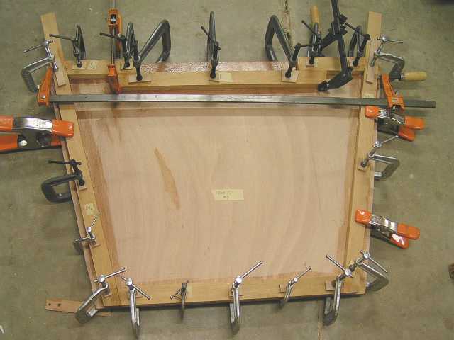
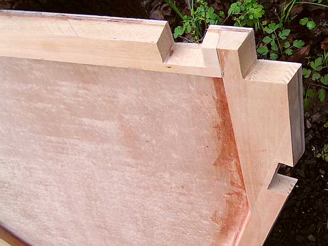
Frame B is shown here, upside down, with the plywood panels being attached to the stick frames. The cross piece at the top of the picture is permanent and the bottom of the boat is attached to this. The other two cross pieces are for construction purposes. The middle one is for this gluing only, and not epoxied. The one at the bottom of the picture (top of the frame) is to maintain the prescribed width while the sides are being attached. One ignores how much junk is in the shop until it is in the back of a picture!
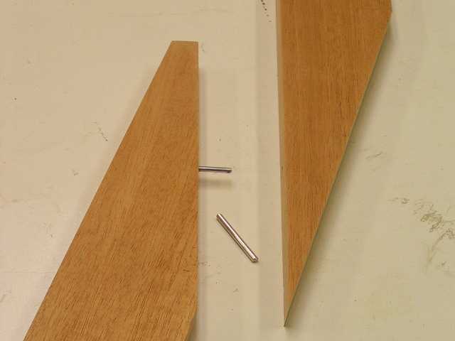
There are places, such as on the sides of frame B, where the clamps are angled to the glue joint. The slippery epoxy allows these joints to move out of alignment. I used small aluminum pins to hold the alignment while the epoxy sets up. They can be left down inside and the outside hole covered. If a future saw cut, or plane, should accidentally hit the pin, it is soft enough to not damage the tool. I use 1/8-inch aluminum welding rod for the pins.
This is frame D that goes behind the aft compartment.
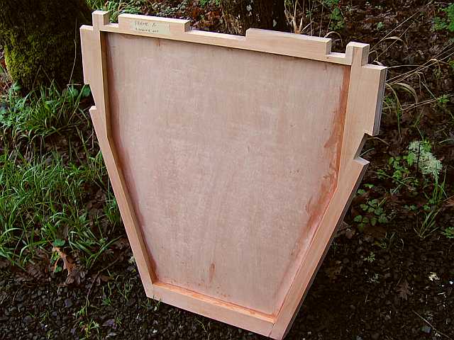
Frame A is at the forward end of the walking slot. The notches are for the various longitudinal members. The frame is 3/4 mahogony with 6 mm Okoume plywood for the panel.
Bevels are cut to the sides, top and bottom to agree with the shape of the boat. The notches reflect these same angles. Most bevel angles come directly from Bolger's plans.
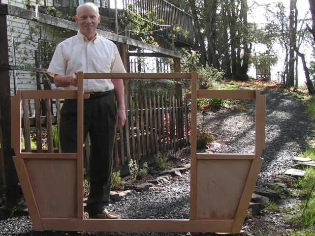
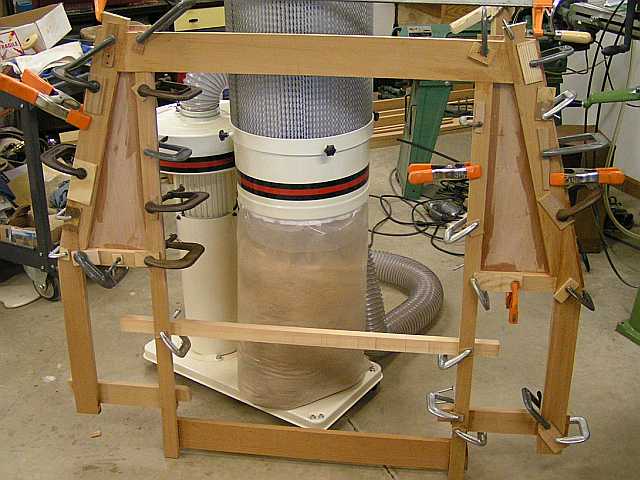
Frame C is located just aft of the point of maximum beam. Thus it reflects the general size of the interior. The average-size boatbuilder is included for reference. The horizontal board across the slot gets cut off after the hull takes shape.
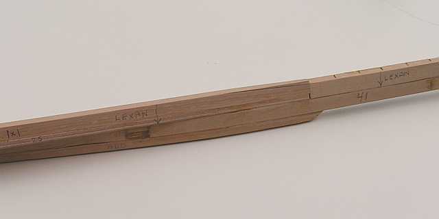
The afterdeck is on top of the hull and overhangs the stern on the sides. The plans do not show the details of the transition from the simple raised deck construction to the more complex afterdeck. So, to better understand this area I made a model of portions of the understructure, as shown here. You are looking from the outside of the boat on the starboard side, and the afterdeck plywood (item 25) is beginning to flare out from the hull on the left of the photo. Part 41 on the right is the raised-deck coaming that supports the plywood side below the middle and the polycarbonate windows above the middle. This part continues aft of the transition at the bottom only. Above the middle, a 1x1 support is added flush with the outer edge of the afterdeck. The window, that is not shown here, comes down to the bottom of the afterdeck plywood.
A longitudinal member has been added below the sheer clamp aft of the transition (marked "ADD"). This makes the bending strength about equal to that of item 41 to increase the fairness of the side. Except at the transition point, where this added part extends 2-inches forward, it is probably not required for strength since the afterdeck is also contibuting. However, I plan to scarf the aft, inner sheer clamp to item 41, to avoid a weak spot at the transition. The afterdeck and the 1x1 above it are just butted against the upper portion of item 41, with a piece of light fiberglass on each side.
Not shown are the sides, the outer sheer clamp (item 9) or the support members under the afterdeck perimeter stiffner (item 27).
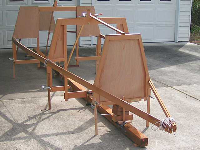
The frames were setup in the driveway. I wish I had a covered area big enough for the boat, but I am willing to wait for reasonable weather and work outdoors. A 20 foot 4x4 was made up from two pieces of pressure treated wood. This was leveled and a centerline marked. The frames were clamped in place, allowing for some adjustment when the side panels are added. The side coaming (item 41) is being dry fitted here, but will be epoxied to the frames at the same time as the side panels to aid in getting a good fit between the coaming and the side panels.
Back to Building Birdwatcher-2 main page
This was last revised 27 May 2005. Bob Larkin, Corvallis, Oregon