Clock setting for the DSP-10
The Need - The two digital modes PUA43 and LHL7 transmit 2 seconds of steady carrier and then shift frequency. The DSP-10 must coordinate the times of transmission and reception to prevent inter-symbol interference. The EME Doppler calculations require a time accuracy of about one second at microwave frequencies. These types of needs push for a built-in clock system with an accuracy of around 20 or 30 milliseconds.
In the past this has been supplied by having a
separate DSP-10 clock
that was manually set before each use. Provision was made to align this
clock to WWV and satisfactory operation resulted. In order to maintain
this accuracy for a period of hours, a clock-speed parameter has been
provided that adjusts the software clock speed to be slightly different
than the PC clock.
UTC Time - Version 3.75 drops all reference to local time. For several functions, such as EME calculations and PUA43 random-stir, to work correctly, the PC clock must be set to UTC (what we used to call GMT!). There is no longer a need for the DOS environmental variable "TZ=". All displays of time are in UTC. The time-type identifier in the lower-left corner of the screen can be set to anything desired, such as "GMT" "UTC" or "Z", by use of the time_str variable in the configuration file.
Three Methods - Starting with version 3.60 of UHFA.EXE, there are three methods for clock operation. The first is fundamentally the same as the previous method as described above. The clock is set manually using the ALT-K clock box, and the clock-speed variable compensates for inherent PC clock speed errors. Internally, it has been revised considerably, and does not use a separate software clock, but rather adjusts the PC clock on a regular basis to keep it as accurate as possible. For the user, this has the advantage of carrying the same clock setting in DOS as in the DSP-10. There is no need to reset the clock if one goes to DOS and returns to the DSP-10.
Method two uses a GPS receiver with an associated 1 pulse-per-second output. The operation is manual, with the operator being prompted through the clock setting operation. The serial-port connection between the GPS and the PC is handled manually using the same port as the DSP-10.
The third method is fully automatic, but requires a hardware switch that was designed by KC7WW and W7CQ. This "borrows" the serial port when needed (typically every few hours) and re-synchronizes the PC clock to the GPS.
All three methods use the clock-speed adjustment to improve the DSP-10 time accuracy over the basic accuracy of the PC clock.
For either method 2 or 3, there must be hardware to place a 1 pulse-per-second signal from the GPS onto the RS-232 DCD line. This is described below.
The following notes describe all three methods.
Clock Setup
The parameters of the clock setting should be entered to the SCRL-F8 dialog box. The use of this box is detailed below. If either GPS setting has been enabled (UT+ or NMEA) it will cause an GPS setting the next time the program is started. In addition, if automatic setting is enabled, by a non-zero minute spacing, the clock will be reset periodically. If a switch box is used, and the parameters are set for periodic updates, the setting of the PC/DSP-10 clock will be totally automatic.
Upon first use, the two parameters of DCD Pulse Polarity and GPS Delay must be determined. If the polarity is backwards, the time set will be in error by the width of the DCD pulse, normally hundreds of milliseconds. If the GPS Delay is wrong, the time set will be in error by an integral number of seconds. Checking against WWV should allow correcting these values. Remember that the ALT-K Box one-second ticks can be brought to the parallel port by setting the address for the LPT port (see the configuration file for lpt_port, and the note there). The ALT-K box can be opened for the GPS case, but the time cannot be changed there. If you want to change time, use the "No GPS" option of SCRL-F8.
Any time one cares to update the clock, and GPS is being used, this can be done manually by SCRL-T, or -t. This is the same setting that is done at startup or periodically.
An information box shows the progression of the update, and also the number of milliseconds of wait for the DCD pulse. This milliseconds will vary with different GPS and is more of a check for consistency than for a particular value.
SCRL-F8 Time Setup Dialog Box
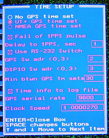
There is a dialog box available for setting the clock parameters, and also the clock rate. This is invoked by SCRL-F8. See the attached scrl-f8.jpg. The parameters are:
Three radio buttons to choose No GPS, UT+ GPS, or NMEA GPS. Either GPS case requires the 1PPS pulse. Selecting one of these disables the other two.
Fall of 1PPS pulse. This determines if the falling edge is used to set the clock. If not checked, the rising edge will be used. Rising and falling is defined here as the level change of the RS-232 DCD signal. Rising is the transition from a negative to a positive Voltage. Note that if one of the common level converters (such as a MAX232) is used between the GPS and the PC, the rising and falling will be reversed.
Delay of 1PPS, sec - This is an integer number of seconds, usually 1 or 2, that allows the 1PPS set pulse to come along after the GPS NMEA time. Often the GPS time data starts at about the beginning of the second for which it corresponds. By the time this is received and processed, the second is well under way, and the next DCD pulse is used for setting.
Use RS-232 Switch. If checked, the DTR and RTS lines will be used to select the GPS and the DSP-10. This is compatible with the KC7WW-W7CQ switch box. There are four possible addresses from 0 to 3 and with the switch box, GPS is 2 and DSP-10 is 3. If this box is not checked, it is assumed that switching is done manually and if a GPS is selected, the prompting for manual switching will occur.
GPS Sw adr, DSP10 Sw adr. These are the two address just referenced.for the GPS and the DSP-10. They can have values, even though the RS-232 Switch is not checked.
Min btwn GPS tm sets. This cryptic collection of letters means the number of minutes between automatic GPS updates. Each update stops DSP-10 screen operation for about 5 seconds. The sounds continue, of course, but the display is not updated, and any transmissions for that time, such as caused by the beacon settings will wait. Thus it is not desirable to do the reset too often. The clock_speed setting continues in use, so for most situations, a reset interval of 60 to 240 minutes is adequate.
Time info to log file. For diagnostics purposes, a file, UTIME.DAT, can be appended to with most of the activities of the clock operation. The format for this file is below. Checking this box causes the file to be written.
GPS serial rate. The serial rate can be different than the 9600 for the DSP-10. Set that here, with values of 300, 1200, 2400, 4800, 9600, and 19200 being allowed.
Clock Speed. This is a modifier to the
clock speed, just like used
for the old DSP-10 clock. If the PC clock runs slow, a value just over
1 will correct this. If it is fast, one just under 1.0 is the answer.
Use the info in the on-line instructions for the DSP-10 to set this,
for now. A new procedure has been added that does the calculations for
clock speed. This is qute a bit simpler than the old hand calculations.
It is described below under
Correcting the PC Clock
Speed
Non-GPS Time Setting (Method 1) - The
procedure for setting
the time in the ALT-K clock-set box is very similar to days of old, but
the 10 msec setting is now the actual PC-clock increment of 55 msec.
The procedure that works well for me is:
It may be convenient to pre-set the time before
loading the DSP-10
UHFA.EXE program. This can be done by the DOS "time" command, or any
other means. The PC clock maintains the time while coming and going
from the program, and setting of the time in the DSP-10 will leave
the time set after program exit. An additional option is to set the PC
Clock from a Alt-% DOS visit. (ALT SH 5)
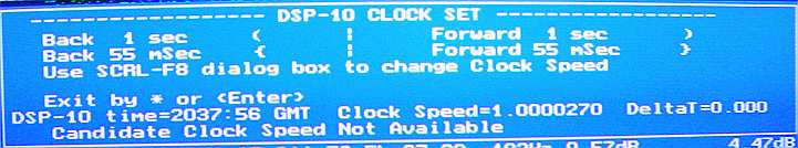
Background: The basic unit of PC time is the 55 millisecond "tick." The { and } keys will now move exactly one tick. The indicated PC time is more complex, has an indicated granularity of 10 msec, and will change by either 50 or 60 milliseconds, when a tick change has occurred. The UHFA program now does tick changes by adding, or subtracting 10 millisecond amounts until the clock changes (by either 50 or 60 milliseconds!). The DeltaT value represents the actual change in setting of the PC clock after a change. For this reason, it may not return to the starting value, after a pair of key hits. A { and } pair of keystrokes will indicate -0.01, 0.0 or 0.01 for DeltaT. They all represent the same PC clock time. This is built into the PC clock, this way!
The ( and ) keys will produce 1 second changes in the same sense as the tick changes. This is also checked by UHFA and in some cases requires a one tick adjustment, that is fully automatic and transparent. In spite of all this, the PC clock's view of a 1 second change is, on the average 1.01, or 0.99 seconds!! This means that changes less than about 5 seconds are correct. Greater changes will differ by about 1%. As long as the clock is within a few seconds of the correct time, when the 55 msec adjustments are made, you will never notice this effect.
The ALT-K Clock Set box can always be opened, but if GPS clock setting is being used there is no control allowed. For manual setting (per the SCRL-F8 box), the clock can be advanced or retarded by either 55 milliseconds of 1 second. This is not quite true, since the clock reading and setting is done with 10 millisecond quantization. So the actual value achieved is accumulated by "DeltaT." It will be observed that if the clock is advanced and then retarded by 55 millisecond, the DeltaT value may not come back to 0, but rather stay with 10 or 20 milliseconds of error. This is just the way the clock works, and so all adjustments are now allow for this effect. After an adjustment the clock is re-read to see what was actually achieved. DeltaT is an example of this.
The ALT-K clock box automatically produces PC
ticks and also pulse
output to the LPT port.
If the lpt_port is 0, there is the computer tick that is hard to hear on laptops. The length of the tick is programmable as tick_time in the .cfg. Don't set this too long (probably 20 or less) as it holds up processing--the computer can't think and hum at the same time!
GPS Time Set (Methods 2 and 3) The GPS time set reads the hour and minute over the same RS-232 serial port as used to communicate between the PC and the DSP-10. Before the GPS time is read, the serial stream from the DSP is stopped. After a time is read the 1 pulse-per-second (1 PPS) signal is used to determine the moment of PC clock setting. This set time will often be 1 or 2 seconds after the read time, and this is allowed for, and set in the SCRL-F8 setup box.
The only difference between the Method 2 manual GPS set and the Method 3 automatic set is the SCRL-F8 item, "Min btwn GPS tm sets." If this is set to zero, there are no automatic sets. Otherwise it determines the number of minutes between automatic sets. For either method, it is always possible to force a GPS set with the Alt-T (or t) command. In addition, if the value is non-zero, there will be a GPS time set in the startup procedure.
Two different GPS formats are supported, the Motorola UT+ binary and the NMEA 0183 rev 2.0. Any GPS that uses either of these should be compatible, but as of this writing, May 2013, only the Motorola UT+ and the Sandpiper NMEA have been tested. In all cases, there is no GPS initialization done, nor is there any serial transmission from the PC to the GPS. In the case of the UT+, the appropriate initialization is the "PS8 1" command, that can come from the Motorola supplied control program.
The NMEA option requires the $GPGSV and $GPGGA sentences. $GPGSV sentences must be received prior to the $GPGGA sentence. A message rate of once every two seconds seems to work well with the Sandpiper. Longer times may also work, if this is not an option.
The proper settings for the Scrl-F8 box have been determined for the two GPS types. For the 1PPS DCD signal, it is assumed that an inverting type of RS-232 converter is inserted between the GPS and the PC. Thanks to W7CQ, WW2R and KD7TS for help evaluating these various species of GPS.
  UT+        Fall of 1PPS   1 second delay    9600 baud
  Sandpiper  Rise of 1PPS   2 second delay    4800 baud (no inversion)
  Jupiter    Fall of 1PPS   2 second delay    4800 baud
1 PPS Hardware - For either method 2 or 3, there must be hardware to place a 1 pulse-per-second signal from the GPS onto the RS-232 DCD line, which is pin 1 of the standard 9-pin D-connector. The voltage level should be RS-232 levels, but otherwise any pulse will do. The software can be adjusted for the polarity and timing of the pulse.
RS-232 Switch Box -KC7WW and W7CQ have designed and produced a PC board for a switch box for the RS-232 lines. This makes a great addition to the DSP-10 when used with any of the GPS units with 1 PPS capability. The software control of the switch is explained above. This makes the inputting of time and lat/lon fully automatic. For DSP-10 compatibility the wiring of the box continues the path of pin-9 "Fast PTT." The box provides TTL to RS-232 conversion for the Motorola UT+ and other units with inverted TTL as well as conversion of the 1 PPS pulse. It also provides for two extra RS-232 devices, that might be useful in the future. Possible uses include programmable RF converters/transverters and antenna az/el control.
Time and Location Bottom Lines - Two new bottom lines are available by SCRL-F3. One is the time data details, and the other is latitude, longitude, height and grid square, derived from the GPS data.
The line for time detail has a quantity dt, which is the accumulated time error due to clock_speed. It is updated once per minute and when it gets big enough to allow a full tick (55 milliseconds) of correction, the minimum a PC allows, it changes the clock. The quantity dt is in milliseconds and changes when the error has built to +/- 35 milliseconds. This error is based on clock_speed only, and does not go to the GPS as an absolute check.
If GPS is being used, the Valid Data flag is shown, along with the number of satellites being tracked and the average S/N of the strong three satellites. This data applies for the last GPS update. This S/N is the power average of the three strongest satellite being tracked. It is in dB, and gives a relative number of the GPS RF performance. Tracking seems to drop out around 30 and 50 is a good number.
GPS age is the number of minutes since a GPS clock set has occurred.
If GPS is not being used, the time data line also shows the number of minutes since an Alt-K clock set was performed. This is not able to make any judgment of the quality of the clock set, of course, and merely means that the Alt-K box was opened.
Clock Configuration File Variables - An asterisk following the variable name indicates that the variable can be set from the SCRL-F8 dialog box. Others are set directly by editing UHFA.CFG
 gps_type *        -1=No GPS being used, 0=UT+, 1=NMEA 0183

 gps_dcd_pol *     0=set time on falling edge of DCD pulse,
                   1=set on rise

 gps_tdelay *      Seconds after time data and before usable DCD edge.

 gps_hund          A small (about 5) offset to adjust for quirks in PC clock setting.

 gps_sw_gps *      Switch setting, DTR and RTS, for GPS. Negative if no switch

 gps_sw_dsp10 *    Switch setting, DTR and RTS, for DSP-10

 gps_baud *        Baud rate for GPS communications,
                   300, 1200, 2400, 4800 or 9600 allowed

 gps_set_spacing * Minutes between automatic setting of the clock from the GPS.
                   0 disables automatic setting.

 gps_ddmm          0 shows latitude and longitude in degrees only ddd.ddddd,
                   1 shows these items as degrees and minutes ddd mm.mm

 gps_ft            0 shows height in meters
                   1 shows in feet

 gps_time_file *   0 no file
                   1 creates a log file of clock set activity
Correcting the PC Clock Speed A new feature is an estimate of the clock_speed parameter without needing side calculations. This involves stopping all GPS clock sets (temporarily), disabling the clock speed correction and doing a pair of manual clock sets, as follows:
1- In SCRL-F8 select GPS-None (the top button of the three)
2- Set Clock Speed to 1.0000000
3- Close the SCRL-F8 box
4- Open the ALT-K box. Set the clock to WWV as precisely as possible
5- Close the ALT-K box
6- Wait a while. One minute is the absolute minimum; several hours is the minimum useful amount; 24 hours should give very precise results.
7- Open the ALT-K box, again. Set the clock again to WWV. The "Candidate Clock Speed" will be displayed that represents the deltaT that was just used to correct the clock. Write this number down, with seven digits after the decimal point.
8- Close the ALT-K and use SCRL-F8 to enter the new clock speed, found in 7.
9- Reset parameters to suit your form of clock setting.
Note, every opening of ALT-K resets this process, so do not open the box until you are ready to do the Clock Speed estimation. The number of minutes since the last ALT-K is shown in the time data line (SCRL-F3) at the bottom.
Clock Logging File - UTIME.DAT - Time File UTIME.DAT is for diagnostic trouble shooting. It records to a file, in the same directory as UHFA.EXE, a summary of operations such as the 1 minute updates, or GPS sets. Each record is a line of ASCII data, with space separated entries as follows (some entries are zero if no GPS is used):
  TM  starts all lines
  record type: 0=minute updates, 2=GPS set, 4=PC clock correction
  day
  month
  year
  hour
  minute
  second
  hundredths of a second
  seconds since 1 Jan 1970
  dt clock error
  seconds since 1970 for last midnight GMT
  clock_speed
  total millisec delay for last GPS set
  gps data valid (LSB)
  number of satellites at last GPS set
  s/n of top 3 satellites at last GPS set
  gps receiver  status (0 if not UT+)
  gps settings (see below)
  text record type and settings again in Hex
If the record type is 2 (GPS time set), the base set, shown above is followed by
  sec.hund of PC clock when GPS time came from GGA message
  sec.hund at DCD 1PPS pulse
  sec.hund after GPS set to sec.00 PC
  milliseconds of delay from gps_msdelay
  milliseconds before first DCD transition (can be 0)
  milliseconds between DCD 1PPS transitions
It the record type is 4 (PC clock update), the base set is followed by
seconds before update of PC clock
hundredths of a second before update of PC clock
    ---- End of record description ----
GPS Settings saved in the file are best seen by converting to binary or hex, as they are arranged by bits. They are also in hex at the end of the entry above called "text record type." The bits show several variables from the configuration file:
Bits 0, 1, 2     gps_type
Bits 3, 4, 5, 6  gps_tdelay
bit 7            gps_dcd_pol
bits 8, 9        gps_sw_gps
bits 10, 11      gps_sw_dsp10
For instance, KD7TS, using a Sandpiper GPS, has 1554, which in binary is 01 10 0 0010 010 or
gps_type=010     (NMEA GPS)
gps _tdelay=0010 (2 sec)
gps_dcd_pol=0    (logic 0 to 1)
gps_sw_gps =10   (2)
gps_sw_dsp10=01  (1)
Clock Set Errors and Warnings The following have been added to track possible errors in the time setting and GPS reading process:
W60 "GGA Parse" The reading of the NMEA sentence GPGGA was not correct. (bug? same as W67)
W61 "DCD Timeout" No 1PPS (pulse per second) signal was found on the DCD line, pin 1 of the 9-pin serial line.
W62 UT+ check sum error in reading the binary data from the UT+ GPS.
W63 UT+ excessive message length meaning bad UT+ binary data was received
W64 GPS time out occurs when no GPS data is received in 5 seconds
W65 GPS fix not established, data was read, but indicated as having no fix in position.
W66 Time set failed meaning that the GPS time and position data was OK, but no DCD pulse occurred within the 1 second window.
W67 GPS NMEA GPGGA sentence error, sub error 1=bad parse, 2=checksum error.
W68 GPS NMEA GPGSV sentence error, sub error 1=bad parse, 2=illegal number of messages, 9=check sum error.
W69 No GPS auto set is available, check the GPS type in the SCRL-F8 box.
E70 Error in creating time logging file.
![]()