Introduction - I put together the control, LO and mixing hardware for the DD4WH "Convolution SDR" receiver [1][2][3]. This uses a pair of Tayloe mixers[4] that are very good in performance, but do require RF filtering to prevent reception at 3-times the intended frequency, as well as the other odd multiples. This requires attenuation at 3-times the lowest frequency where the filter is to be used. For instance, if the filter is to pass the 3.5 MHz bottom edge of the 80-meter amateur band, attenuation must be significant at 10.5 MHz.
Other receiver architectures need some front-end selectivity as well. These little filters do not
provide the selectivity that a series of band-pass filters would. But, if an octave filter is adequate,
the simplicity and lack of tuning of these filters is appealing. The term, adequate
is also dependent on the antenna that is being used and the closeness of interfering transmitters.
I have not tested these filters for transmitting applications. They certainly would be limited to a few Watts by the dissipation in the SMD inductors. But, there is room for small toroidal inductors of the T25 size, and that might make these work in the 5 or 10-Watt RF power range. Someone might want to explore this.
The design objectives were:
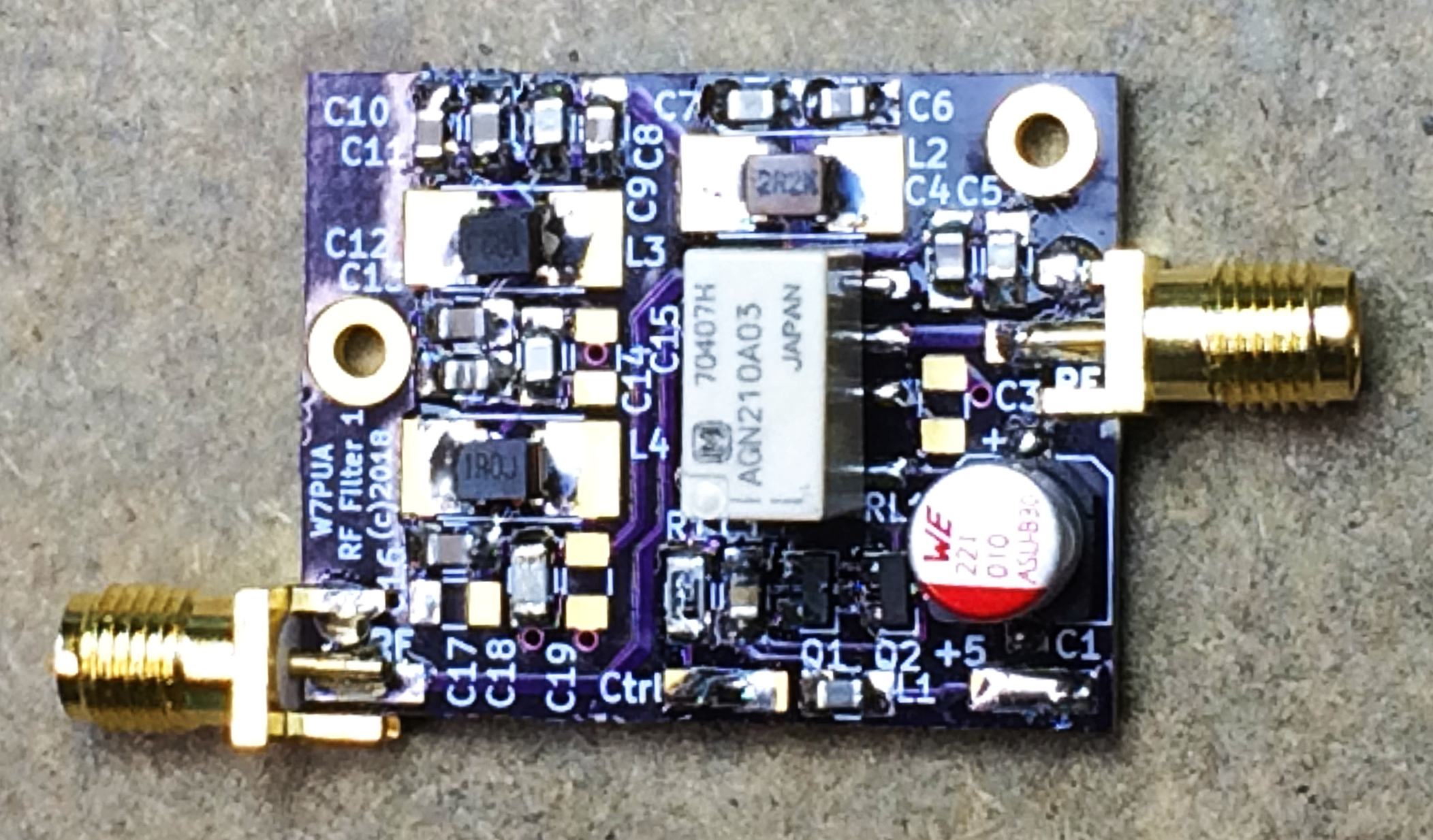
Parts - All capacitors except C2 are 0805 NPO/COG SMD. Capacitor pads will handle either 0805 or 1206 size. Be sure to use NPO/COG ceramics. Inductors are 1210 SMD types. I attempted to maximize Q and temperature stability. The parts selected were made by TDK and referred to as NLV32-EF type. For instance, the 1 uH value is TDK NLV32T-1R0J-EF and Digi-Key 445-16564-1-ND. Pads for inductors will handle 1206, 1210 or almost any larger size. They also provide enough space for T25-x toroids, although such were not used for the results shown here. Capacitor and inductor values are listed below, along with the measured responses, for each of the 3-filters built so far. The transistors, Q1 and Q2 are MMBT3906 and MMBT3904. These fit the SOT-23 pads. L1 is a ferrite bead, 0805 SMD, Murata BLM21PG331SH10 or Digi-Key 490-7823-1-ND. The DPDT latching relay with 3-Volt coil is Panasonic AGN210A03Z, Digi-Key 255-3356-1-ND. C1 is 220 uF, 10 Volt SMD, Digi-Key 7323-8492-1-ND. C2 is 0.47 uF, 0805 SMD, 25+ Volts such as Digi-Key 127674.
PC boards are available from OSH Park in multiples of 3 for about US $7.
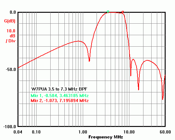
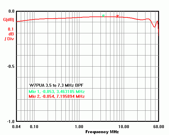
3.5 to 7.3 MHz Filter - This filter covers 3.5 MHz to 7.3 MHz for the 80/75-meter and 40-meter ham bands as well as various services such as WWV at 5 MHz. I studied the tradeoffs for Cauer/elliptic filters to maximize the rejection of the MF AM broadcast band. While still passing 3.5 MHz, the worst-case rejection below 1.6 MHz was only about 25 dB. Depending on how close and powerful such broadcast stations are, this may not be adequate. It was decided to not add to the complexity of all the filters because of this potential problem. One can add a separate reject filter in cascade if needed.
Capacitor and inductor values are listed here, with values rounded
to standard values. See the Parts notes above
for more information on these components.
C4 = C8 = 470 pF  (HPF)
C5 = C9 = 680 pF
L2 = 2.2 uH     C6 = 2700 pF   C7 = 3300 pF
C10 = 220 pF      (LPF)
C11 = 220 pF
L3 = 1.2 uH     C12 = 51 pF    C13 = 33 pF
C14 = 680 pF    C15 = NU
L4 = 1.0 uH     C16 = 220 pF   C17 = NU
C18 = 330 pF    C19 = NU
The following 50-Ohm transmission response was measured using an N2PK Vector Network Analyzer and G8KBB myVNA software. The third null on the high frequency side is believed to be the result of a stray resonance in the series inductor of the HPF. It is not part of the LPF response.
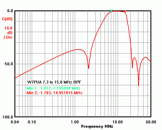
7.3 to 15 MHz Filter - This filter covers 30 and 20-meter ham bands as well as the heart of short-wave broadcast.
Capacitor and inductor values are listed here, again with values rounded
to standard values.
C4 = C8 = 470 pF  (HPF)
C5 = C9 = NU
L2 = 0.82 uH    C6 = 3300 pF   C7 = 3300 pF
C10 = 220 pF      (LPF)
C11 = NU
L3 = 0.58 uH    C12 = 22 pF    C13 = 18 pF
C14 = 330 pF    C15 = NU
L4 = 0.47 uH    C16 = 56 pF   C17 = 56 pF
C18 = 82 pF     C19 = 82
And the measured results:
15 to 30 MHz Filter - Our third filter covers the 17, 15, 12 and 10-meter ham bands. The same deal as above for component values:
C4 = C8 = 120 pF (HPF)
C5 = C9 = 120 pF
L2 = 0.47 uH
C6 = 2200 pF    C7 = 1000 pF
C10 = 100 pF     (LPF)
C11 = NU
L3 = 0.33 uH    C12 = 10 pF    C13 = 10 pF
C14 = 82 pF     C15 = 82 pF
L4 = 0.22 uH    C16 = 56 pF    C17 = NU
C18 = 82 pF     C19 = NU
In the following measured plot, note the pass-band roll-off at the 30 MHz end. This is the result of the lower Q of the two LPF inductors, L3 and L4. If one wanted to experiment with higher-Q powered-iron toroids, this would be a good place to start.
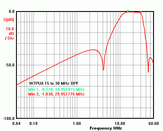
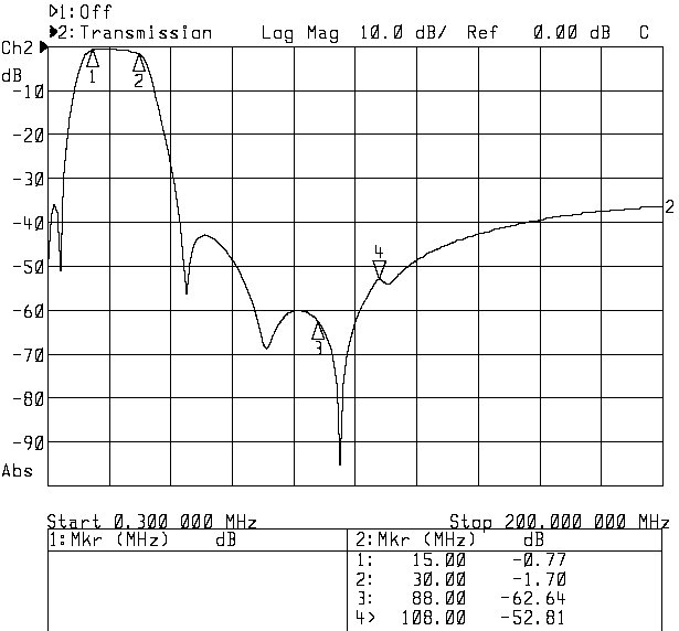
The N2PK VNA covers up to 60 MHz. For this 15 to 30 MHz filter I wanted to look higher, as the rejection of the strong signals in the FM broadcast band is important. Here is a plot from a different VNA, an HP-8714B, showing the response up to 200 MHz. Note that the previous plots have used log frequency scales which are not available on the HP analyzer and so a linear frequency scale is used, so they look different.
Relay Bypass response - When the relay is in the bypass position, we would like low insertion loss. This plot is for the 3.5 to 7.3 MHz filter, but the other two look about the same. The loss in the HF region is less than 0.1 dB, fully supporting the idea of arranging the filters in cascade. The following is the measured insertion loss:
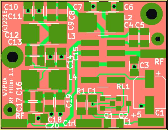
Construction - The PC board in the picture at the top of this page simplifies construction and minimizes lead lengths. In the board drawing below, the red-ish color is the solid bottom copper ground plane, the greens are top traces and the white is the top silk screen part markings.The smallest capacitors at 0805 and inductors at 1210 size require some care that the terminal ends overlap the pads. There is lots of room, so this is easy to do. All four off board connections are made to long pads at the board edge, marked RF, +5, Ctrl and RF. The in and out ends are reversible. Ground connection pads are next to the RF connections pads. Two mounting holes are provided, big enough for 2-56 or m2.0x0.4 screws.
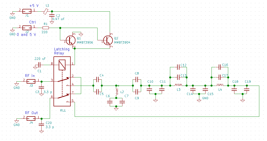
Design - The overall filter topology is a cascaded high pass filter (HPF) and a low pass filter (LPF). The HPF has series capacitors on the input and the output sides along with a series L-C to ground in the middle. This produces a null at some selected frequency in the stop-band. The LPF uses three shunt capacitors along with two parallel L-C circuits between the shunt capacitors. This produces a pair of nulls in the stop band. These two cascaded filters taken together define a band-pass filter shape. This arrangement was used as it provides flexibility in the shapes of the two stop-bands.
There are computer programs available to design L-C filters and simulate the results. I did not use a design program, but rather worked from tables of Cauer-elliptic prototype designs [5][6][7]. These designs were scaled to the cut-off frequencies needed and to 50-Ohm impedance level. This involved doing some tradeoffs for the HPF between the stop-band attenuation and the upper frequency limit for the stop-band. In particular, the first filters stop band needed to come up to 1.6 MHz to cover the AM broadcast band. The maximum attenuation that met this criteria was 25 dB, and even that required taking a few tenths more attenuation at 3.5 MHz than was desired. The second and third filters with higher frequency pass-bands, are able to have 35 dB or more attenuation in the AM band.
In all cases the schematic shows two capacitors in parallel. This was done primarily to make the selection of values more flexible. For each pair, either all the capacity should be in a single capacitor, or the two values should be kept as close together as much as practical.
When the relay is in the bypass position, the path through the board appears as an inductor. The impedance match can be improved by making this one element of a three component LPF. C3 and C20 do this having values of 3.3 pF. The cut-off frequency of the LPF is well above the frequencies where this board would be used.
The latching relay has a single coil and the position of the relay is determined by the direction of the current through the coil. The The current needs to flow for only a few milliseconds. The drive circuit seen in the schematic above uses an NPN/PNP pair of emitter followers Q1 and Q2, to pull one end of the coil close to either ground or +5 Volts. The voltage across the 220 uF capacitor, C1, will move to ground or +5 Volts also, and current will cease. The next time the control voltage changes, almost the full voltage will first be applied to the coil. This circuit is reliable as long as (a) it is initialized by doing a par of voltage changes at startup, and (b) that sufficient time elapses between changes to charge/discharge C1, typically 1 second.
[An aside: I first was shown this fine relay driver circuit by a ham (I can't remember who, but he did not claim to have originated the circuit) at the 1988 Microwave Update. Does anyone know of the origins of this?]
Notes:
On the Design of Filters by Synthesis,R. Saal and E. Ulbrich, IRE Transactions on Circuit Design, December, 1958. This paper also has extensive tables of prototype Cauer-elliptic LPF.
Handbook of Filter Synthesis,Anatol Zverev, 1967. The tables are extensive, but the text is not light reading!
Simplified Modern Filter Design,Philip R. Geffe, 1964.
Issued 16 March, 2018. - All Copyright © Robert Larkin 2018