Diplexer for transverters, 144 and 10 MHz
Use a single coax to transmit three signals.
This diplexer is one of a pair used to share a single coax cable running from the ham shack to a microwave transverter located 150 feet away, at the antenna. Three separate lines could be used, but it is simpler and easier to maintain a single coax and a diplexer at each end. The 144 MHz signal is the i-f going to and from the transverter. The 10 MHz signal is a frequency reference used to keep the transverter conversion oscillator exactly on frequency. In addition there is a DC port that I use for transmit and receive control. In that sense it is really a triplexer, but the DC part is simple, making the "tri" trivial.
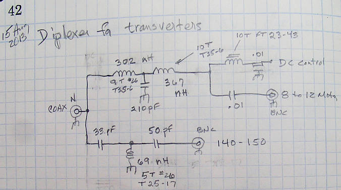
The topology that was chosen is a combination low-pass (LP) and high-pass (HP) filters, joined at the common coax. In order for the LP-HP pair to work together, the HP starts at the coax with a series capacitor and the LP starts with a series inductor. Based on standard roll-off curves, a three-pole filter was chosen for each. The heavy lifting was done by the ARRL Radio Designer program, using the following script:
**************************************************************
* Diplexer 144 and 10 MHz   RSL 15 Aug 2013
**************************************************************
CH1: ?10PF 32.9814PF 60PF?
CH2: ?10PF 50.3336PF 80PF?
LH: ? 30NH 69.4194NH 600NH?
CL: ?60PF 209.579PF 360PF?
LL1: ?120NH 301.594NH 2000NH?
LL2: ?120NH 367.2NH 2000NH?
*
BLK
* HP/LP Diplexer, with 1 as common port
*   HP:  1  31  3
*   LP:  1  21  2
IND 2  21   L=LL1  Q=100  F=40MHZ
CAP 21  0   C=CL
IND 1  21   L=LL2  Q=100  F=40MHZ
CAP 1  31   C=CH1
IND 31  0   L=LH  Q=100  F=40MHZ
CAP 3  31   C=CH2
DIPLEXER:3POR 1 2 3
END

FREQ
STEP 5MHZ 200MHZ 1MHZ
END

OPT
DIPLEXER
* High Pass
F=140MHZ 150MHZ  MS11=-20DB LT
F=140MHZ 150MHZ  MS31=0.0DB W=2
* Low Pass
F=8MHZ 12MHZ  MS11=-20DB LT
F=8MHZ 12MHZ  MS21=0.0DB W=5
* Try to enforce some rejection
F=140MHZ 150MHZ  MS21=-50DB LT W=4
F=8MHZ 12MHZ  MS31=-50DB LT  W=8
END
Radio Designer was run including first Random optimization, followed by Gradient optimaization. The following schematic resulted. The schematic includes the DC ferrite coil and the associated feedthrough bypass. Otherwise, it is the same as the design script.
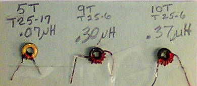
The coils were wound on small T25 size powdered iron toroids. These values were measured, and the turns adjusted in spacing to get the desired inductance.
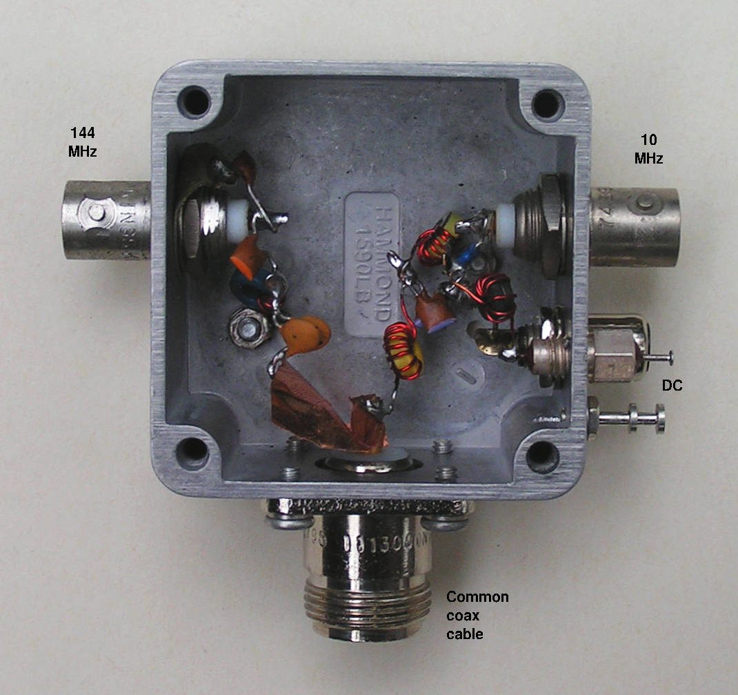
Holes were drilled in a Hammond 1590LB box, including points
for the ground terminals. The asssembly was done attempting to keep
capacitor leads short. One place where that did not wor out well
was between the type-N connector on the common coax and the 33 pF cap
for the HP filter. This was partially made up for by connecting with a
tab of thin copper metal.
Our job is not done until we measure the diplexer and do any necessary tune up. Here is the transmission to the 10 Mhz port, from the common coax connector.
And the same measurement to the 144 MHz port:
The most sensitive (easiest to tune from) of the measurements is reflection. We can see both the 10 and 144 MHz reflection at the common port. It was found that the 144 MHz reflection could be iproved by a few dB by adding a 2.2 pF capacitor from the 144 MHz BNC to ground (not shown on the schematic, above). It is not unusual to discover benefit in matching by adding shunt capacitors. This tends to compensate for stray series inductance in the lead going to the connector. The following shows reflected power for the common coax port:
This page was last updated 23 Aug 2013.
Copyright 2013, Bob Larkin W7PUA. Please email comments or corrections to bob 'the at sign' janbob dot com