Introduction - The development of the Controlled Envelope Single Side Band (CESSB) was done by Dave Hershberger, W9GR. The following description is borrowed from the writings of Frank, DD4WH that is on line at the GNU Radio site.
Controlled Envelope Single Sideband is an invention by Dave Hershberger W9GR with the aim to "allow your rig to output more average power while keeping peak envelope power PEP the same". The increase in perceived loudness can be up to 4dB without any audible increase in distortion and without making you sound "processed" (Hershberger 2014, 2016b).
The principle to achieve this is relatively simple. The process involves only audio baseband processing which can be done digitally in software without the need for modifications in the hardware or messing with the RF output of your rig.
Controlled Envelope Single Sideband can be produced using three processing blocks making up a complete CESSB system:
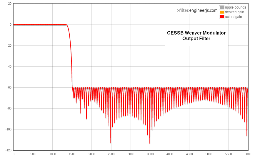
1. An SSB modulator. This is implemented as a Weaver system to allow minimum (12 kHz) decimated sample rate with the output of I & Q signals (a complex SSB signal).
2. A baseband envelope clipper. This takes the modulus of the I & Q signals (also called the magnitude), which is sqrt(I * I + Q * Q) and divides the I & Q signals by the modulus, if the signal is larger than 1.0. If not, the signal remains untouched. After clipping, the signal is lowpass filtered with a linear phase FIR low pass filter with a stopband frequency of 3.0kHz
3. An overshoot controller . This does something similar as the envelope clipper: Again, the modulus is calculated (but now on the basis of the current and two preceding and two subsequent samples). If the signals modulus is larger than 1 (clipping), the signals I and Q are divided by the maximum of 1 or of (1.9 * signal). That means the clipping is overcompensated by 1.9 which leads to a much better suppression of the overshoots from the first two stages. Finally, the resulting signal is again lowpass-filtered with a linear phase FIR filter with stopband frequency of 3.0khz
This CESSB system can reduce the overshoot of the SSB modulator from 61% to 1.3%, meaning about 2.5 times higher perceived SSB output power (Hershberger 2014).
The Teensy Implementation The description above, along with the Hershberger papers, referenced below, tell the story of how the CESSB process works and why the 3 or 4 dB in average power is possible. We won't repeat that here, but rather explain the implementation used for the Teensy floating point (F32) audio library (see also the associated Design Tool). The library class for the direct implementation of the procedure is called "radioCESSBtransmit_F32." Note that an associated library class is described below that differs in not using the Weaver method of SSB generation.
Many radio implementations using the F32 library work at a 48 ksps sample rate. The current implementation is designed for that rate. However, this rate is too high to be efficient in some of the spectral filtering needed for CESSB. The initial step is therefore to decimate the data to a 12 ksps rate used in the Weaver modulator. Speech audio for communication systems is typically limited to about 3 kHz so that sample rate is quite adequate. The Weaver modulator doubles the number of signals, but cuts the bandwidth of each in half to less than 1500 Hz [1].
The second stage of CESSB is to use limiting and low pass filtering on the two Weaver outputs. Limiting is a non-linear signal process and requires a higher sample rate. Here we use DSP interpolation to increase the sample rate to 24 ksps which processes signals up to 8 times the Weaver bandwidth. The limiter works on the magnitude of the I and Q signals envelope and clips them to the defined maximum level of 1.0.
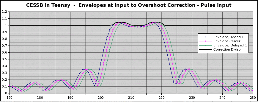
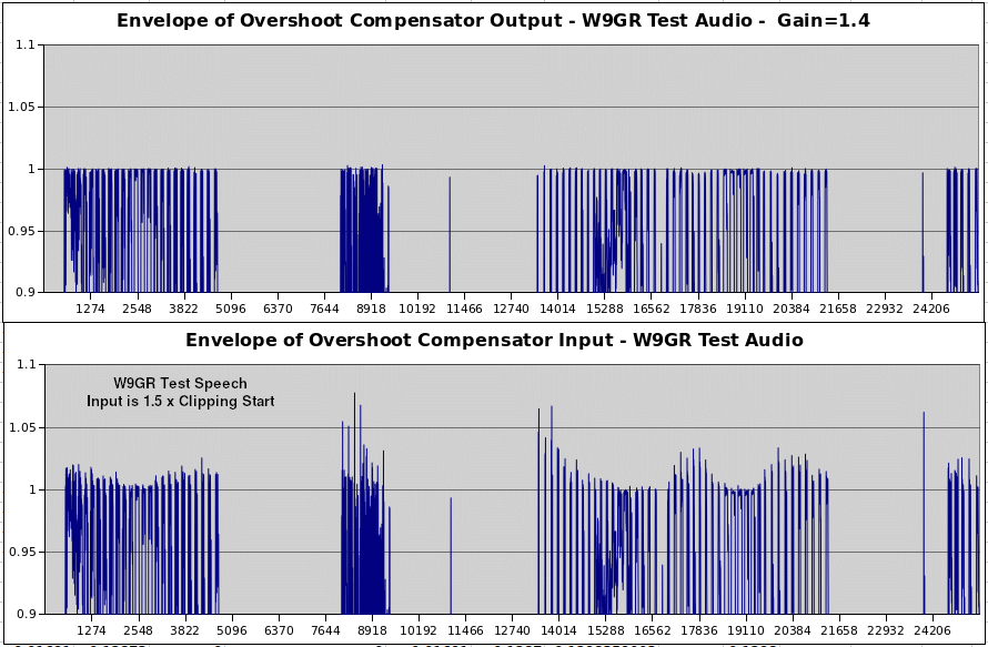
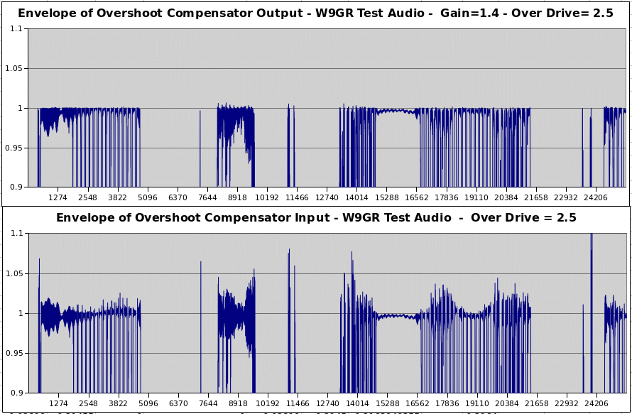
At this point, we have an old-fashioned SSB clipper/filter. It has re-growth of envelope peaks, as described by Hershberger. The Overshoot Compensator is next. The Teensy F32 library implementation uses the method suggested by Hershberger that only filters the overshoot signal, preparing it for subtraction. An 125 coefficient FIR filter is used for this filtering and introduces a delay. This is compensated for by a 62 sample delay array that is in a 64 element circular array. The overshoot compensation looks at the envelope both ahead and behind the time of the signal center. This requires a 4 element circular array. To test the alignment of these delays, a test pulse was used. This consists of 312 uSec at the + level followed by 312 uSec at the minus level. The levels are chosen to be equivalent to 3dB average power increase. The resulting envelopes are shown below.
After Overshoot Correction, the I and Q output signals are interpolated back up to a 48 ksps sample rate, ready to go forward in the audio stream.
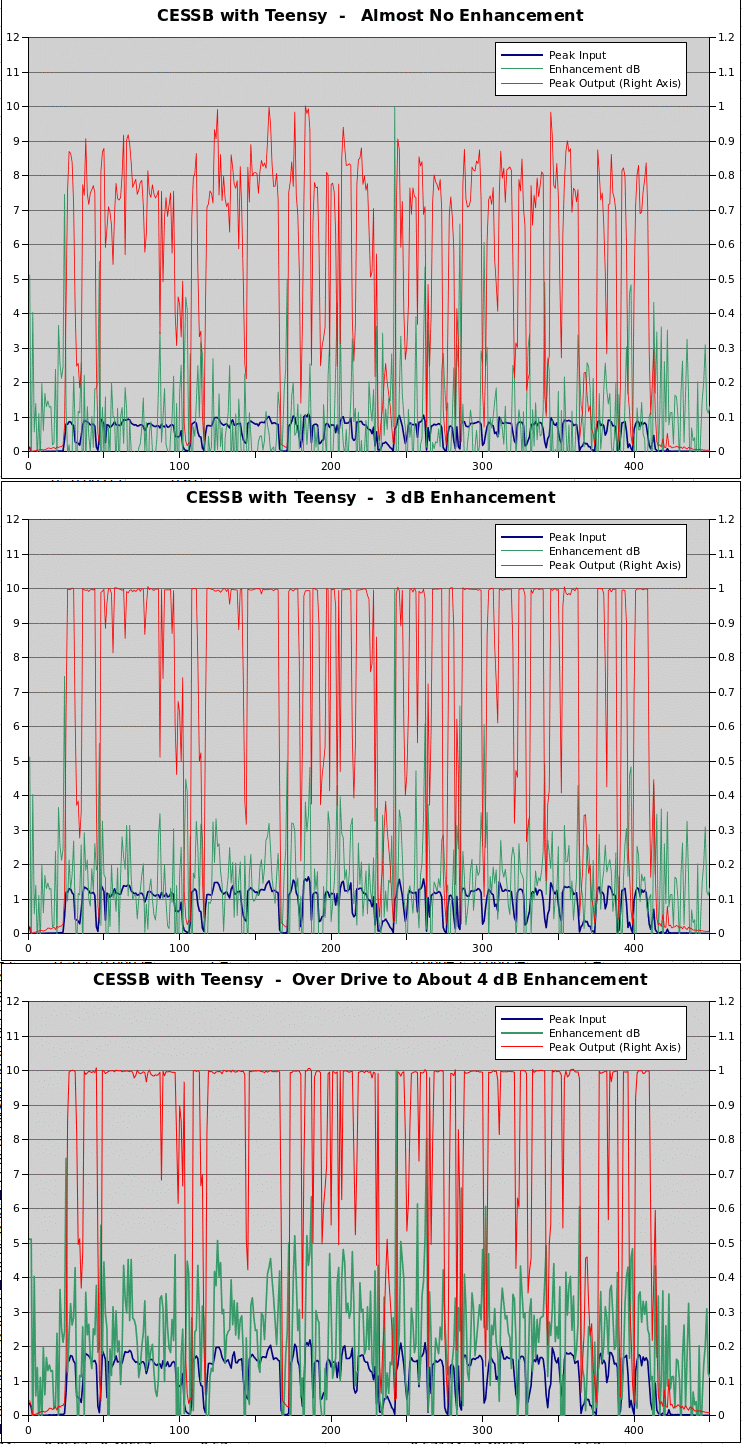
The envelope at this point is constrained very close to 1.0. The test INO was run using the 12 second W9GR test voice signal. The following three graphs show the basic performance as the drive is increased by 1.5 and 2.0 voltage ratios, corresponding to the names 3dB and 4dB of enhancement. It might be noted that further overdrive to, say, 3.0 times the clipping start is not catestrophic. Clipping continues to limit the peak output, but the sound starts to deteriorate and some out-of-band spectral products are enhanced. The latter will be discussed more below.
Spectra for Voice Input The Example file CESSB1.ino was used to measure the spectrum of the process after it had been converted to a 15 kHz "carrier" frequency. This conversion allows easy visualization of the signal, the opposite sideband and the adjacent spectral space. The graph below shows the spectrum for four levels of drive.
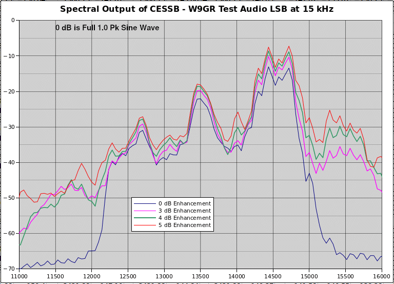
Note that the 0 dB enhancement curve shows the opposite, USB region, to be generally 55 dB or more below full scale. This indicates that the measured results will be the result of the CESSB process and not other error sources. The voice spectrum shows several peaks around 300, 600, 1500 and 2300 Hz below the carrier frequency. This is typical for a voice signal. Looking above 15 kHz we see the upper or opposite sideband. Ideally there would be no spectral power above 15 kHz. But we do see power peaking 300 to 500 Hz above 15 kHz. This increases with increasing drive and for 4 dB enhancement is roughly 20 dB below the transmitted signal or 32 dB below a full sine wave. The graph is not showing it, but the spectra continues to fall off quite fast beyond the region shown. The spectrum down to 12 kHz belongs to the main LSB, and below that power drops off considerably. We could speculate that this drop off might be less for a higher pitched voice than the W9GR sample. Likewise, the sample shown probably enhances the upper sideband more than many voices would.
We can speculate that this spreading of the spectrum is from phase errors generated in the clipping operations, or to some degree from the non-linear amplitude distortions to the waveform. What is most important, perhaps, is that the power level of these out-of-band outputs are generally below the intermodulation (IM) distortion spectrum produced in follow-on amplifiers. Note that if there is special circuitry to reduce the IM level of follow on amplifiers, it would be desirable to evaluate the contribution of CESSB to undesired spectra.
The amount of average power enhancement can be estimated from the FFT spectral plots. In all cases the peak power out is virtually the same, meaning that changes in the spectrum is due to changes in average power. Using that idea and a magnified version of the above graph, it was confirmed that 3, 4 and 5dB are close to the enhancement values.
Two-Tone Testing It should be pointed out here that the CESSB system was intended for voice enhancement, and pulse and two-tone testing is outside that range of signals. It remains that those other controlled signals can be very valuable to understand the CESSB sytem operation and its performance. To do two-tone testing a pair of equal sine waves were inputted at 468.75 and 703.125 Hz. These strange frequencies were selected to hit in the middle of FFT bins. A 1024 point FFT was used for measurement with 46.875 Hz bin spacing. Here is a graph of the two tone spectra with the enhancement values being the voice enhancements for the same amount of peak over drive.
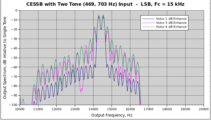
Two tone tests do not have any time when the waveform is not full strength. But there is a fast variation in envelope. The patterns in the graph above suggest it might be a good way to characterize the CESSB side spectra. This is a good area for further study.
Application of CESSB The I-Q output of the CESSB lends itself to being used with an intermediate I-F in DSP. The ideal DSP multiplier mixers will not add any mid-point tones. Follow on processing, either digital or analog should avoid any sharp narrow-band filtering or overshoots may result. With superhet architecture it should be possible to adequately maintain the envelope control that the CESSB output produces.
Direct output from the Weaver-based CESSB to zero-IF hardware, however, can result in mid-band (1350 Hz) tone problems due to LO leakage in the hardware mixers. The tone location at mid-band and the limited LO-RF isolation in many mixers makes this a problem. Again, note that this issue does not arise with mixing in DSP as LO leakage in a multiplier is inherently very low. But this leads to the next topic of using the phasing method of SSB generation to avoid the mid-band tone.
An alternate Phasing Method CESSB The Weaver method of SSB generation was used by Hershberger in his papers. This is attractive from the point of computational efficiency. At the level of DSP accuracies it is mathematically equivalent to the phasing method and does not have a lower input frequency limit as do Hilbert transform based phasing designs. But, as discussed above, the mid-band tone issue calls for a phasing design when used with zero-IF hardware . So, such an element was added as a separate class called, "radioCESSB_Z_transmit_F32." This is very similar in structure to the Weaver version decribed earlier. All the filtering is different as the phasing method must deal with the full audio bandwidth. The output is either LSB or USB with the non-carrier at 0 Hz. To support input audio frequencies down to 150 Hz, a 201 tap Hilbert filter was used. On a Teensy 4.x the processing load of this object is only 8% of available real time meaning that it would also run easily on Teensy 3.5 or 3.6.
After a bit of fiddling, the various delays of the new procedure were worked out and various tests performed. Voice input is the most important test to run, but symmetrical pulses and two-tone tests provide views of the process in the time and frequency domains, respectively. The former is invaluable for being sure all the delays are proper. The final voice input tests were run at a variety of levels and again showed the effeectiveness of the CESSB process. The phasing method class, as expected, was very similar in performance to the Weaver based class. The following graphs show detailed views of the output portion of the process, confirming the envelope control.
One area that the Weaver and phasing-method classes differ is the correction of external errors and sideband selection. For the Weaver case the sine-cosine generators is used to adjust relative phase for both error correction and for changing sidebands. For the phasing method, the sideband selection was moved to a +/- sign for one channel while phase errors were put into cross coupling between the I and Q channels. Another area that was explored using the phasing method was the gain for the overshoot compensation. The commonly used value around 1.9 was found to be somewhat too high, causing slight lowering of the average power. After several tests, a value of 1.4 was found to still not leave overshoot remnants and so, was adopted as the default for this class. This issue needs to be revisited for the Weaver method.
Last thoughts I recommend that a CESSB object be included in SSB designs using the Teensy F32 library. It may be useful to turn the block on and off, but a better method would seem to leave it in and cut the drive level. That gives good protection of amplifier overdrive and no cost. But, if excessive inputs do occur, the CESSB prevents splatter problems. Using 3 to 4 dB of CESSB enhancement can be used with minimal issues. That corresponds to about 2:1 voltage overdrive (above the start of clipping). Some spectral broadening occurs, but that is under normal linear amplifier distortion, and drops very rapidly going away in frequency from the transmitted signal. Considering the 3dB of increase in average power, the on-the-air sound of the CESSB processed signal is very good.In general, a Compressor2 object should precede that for CESSB. That allows good control of the input level and compensates for voice ups and downs.
Thank you - Of course huge thanks to Dave Hershberger, W9GR, for developing the system and making the information available. Thanks to Mike K7MDL for testing the process in a zero-I-F transmitter. Also, to Rick KK7B and Ray W7GLF for helping make this document correct. And to the folks at PJRC for making the Teensy hardware and software available. Bob Larkin W7PUA
References:
Issued 6 February 2023. - All Copyright © Robert Larkin 2023