Birdwatcher-2 Building the Tiller Mechanism and Rudder
Birdwatcher-2 Sailboat, designed by Phil Bolger
The steering of the Birdwatcher-2 (BW-2) is accomplished by a conventional kickup rudder. Do to the double ended hull, the tiller must be moved forward of the rudder pivot point. This is accomplished by placing pulleys on both the top of the rudder and on the end of the tiller. The tiller is inside the boat and the two pulleys are connected together by 1/4 inch line placed under tension by turnbuckles. This page has details of all these parts.
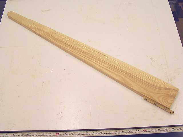
The tiller was constructed from Eastern Ash. It is about 33 inches long. The handle end has been sanded to be a good hand grip. Part of the bronze hinge for attaching to the pulley is shown. Varnish has not yet been applied.
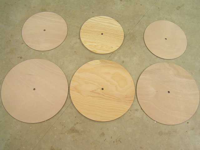
The center 1/2 inch thickness of the pulleys was made from Douglas fir marine plywood. The outer sides are 6 mm Okoume plywood. The center cores are 1/2 inch smaller in diameter than the sides to form a guide for the steering lines. These 6 pieces were rough cut on a band saw and finished with a router. The 1/2-inch hole in the centers forms a bearing for routing. A fixture was made to hold the 1/2-inch guide shaft.
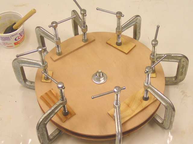
Epoxy glue-up of the 12-inch pulley sandwich for the rudder is shown here. Light grease on the 1/2-inch bolt through the center allowed later removal.
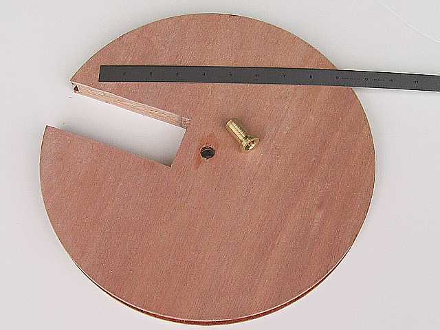
The 12-inch diameter pulley will be attached to the rudder case in the rectangular slot. The 1/2-inch center hole was re-drilled to take the brass insert bearing that is shown. This was a 1-1/4 inch long piece of 3/4-inch diameter rod (Small Parts, Inc) that was turned down to 1/2-inch diameter over 1-inch of the length. The remaining quarter inch serves as a flange to keep the bearing in place. What looks like threads on the bearing sides are actually small grooves to catch epoxy, helping make the part permanent after it is placed in the pulley. The center hole in the bearing is drilled to 25/64-inch to take a long 3/8-inch stainless steel rod that doubles as rudder pintles.
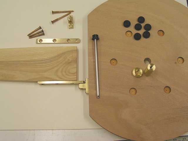
The 16-inch diameter pulley is cut flat for 10-1/2 inches. The tiller is attached by a home-made hinge. Two straps 1/4 x 1/2 x 4-3/4 are screwed to the sides of the tiller, with one attached here. the pulley side of the hinge was made from 1/2 x 1-inch stock. All four hinge parts are drilled to 17/64-inch to take the 1/4-inch stainless pin shown. This allows rapid removal of the tiller. A rudder lock to substitute for the tiller is planned, eventually, and would use these same attachment points to the pulley. The 3/4-inch pulley bearing, shown near the center of the pulley provides support from the rear deck of the boat. It is retained from the top by the 1-inch diameter disk shown. The bottom of the bearing is tapped 3/8-16 to allow retention of the pulley with a washer. The six black bumps are teflon bumpers (UHMW would be as suitable, depending on what was around the shop). These go into the holes on the top of the pulley to provide extra support for the bearing. These bumps were not shown on the plans and may be unnecessary insurance items. They are 3/4-inch diameter with rounded tops.
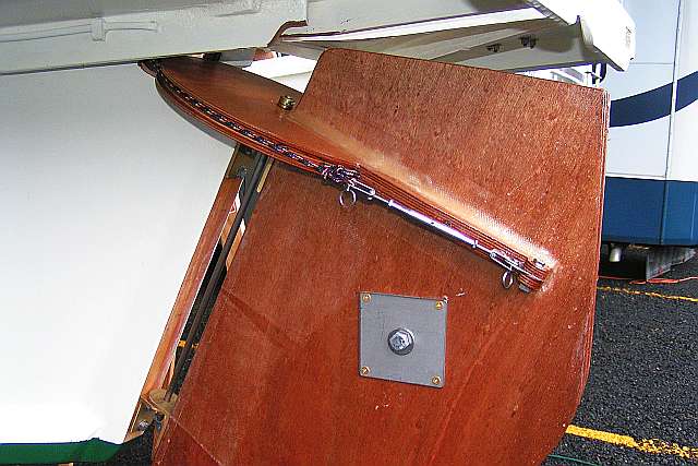
The fold-up rudder is sandwiched by the cheeks. A rudder bearing is fromed by two pieces of 1/8-inch stainless steel. The shaft is a 1/2-inch stailess bolt that goes through the bearings and the cheeks. Pintles and gudgeons are formed with bronze angle and a stainless rod.
I put the adjusting turnbuckles here on the rudder. They were drawn as being in the wet locker. I tried this, but really ran out of room. This outside location is easier for adjustment, and can even be adjusted on the water by lying on the afterdeck.
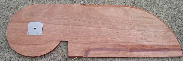
Formed from three pieces of plywood, the rudder is 1-inch thick. There is an up haul to raise the rudder, and since it is lighter than water (there is no rudder ballast) there is also a downhaul. The latter makes its way through a pair of blocks on the starboard rudder cheek to a soon-to-be-installed auto-release rudder cleat. The cleat will be in a vacant spot, low in the motor cutout.
Back to Building Birdwatcher-2 main pagePage
This was last revised 2 May 2007. Bob Larkin, Corvallis, Oregon