Birdwatcher-2 Interior Construction
Birdwatcher-2 Sailboat, designed by Phil Bolger
One-inch polystyrene foam is used on all surfaces inside the BW-2. This insulates the boat from outside temperatures, reduces the sound of water against the hull, makes the boat unsinkable and adds considerably to the strength of the structure, without adding much weight. This page discusses the issues and methods for installing the foam and the plywood covering.
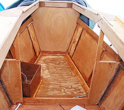
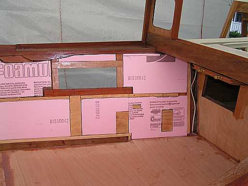
This is the forward compartment, ready for foam installation. It works well to build a frame around the foam to define the edges of the foam and to glue the inner 3 mm plywood to, eventually.
The battery box is just forward of frame B on the port side. A water path has been left aft of the battery box that flows through the bulkhead and into the gutter in the middle compartment. I elected to use only one battery, and to make up the weight of a second battery with 7 one gallon water bottles, held in a pair of racks next to the battery. These racks will be built after the plywood covering is in place.
The coaming along the slot is made from 12 mm okoume plywood. It looked a bit unfinished, so I found some 'L' trim that fit. This trim is hemlock and needs some stain to turn it into faux mahogony. In this picture, the trim can be seen in most of the forward compartment. As of this writing, it extends the full length of the slot, and looks better than the plywood edge!
The aft compartment framing includes the oar ports. This is the starboard side. The gutter stops at the aft edge of the oar port, as it serves little function as one goes farther. The two blocks at the aft end, a few inches up, are backing pads for the foot braces used in rowing. After the wall is finished, the foot braces will fasten to these blocks through the plywood.
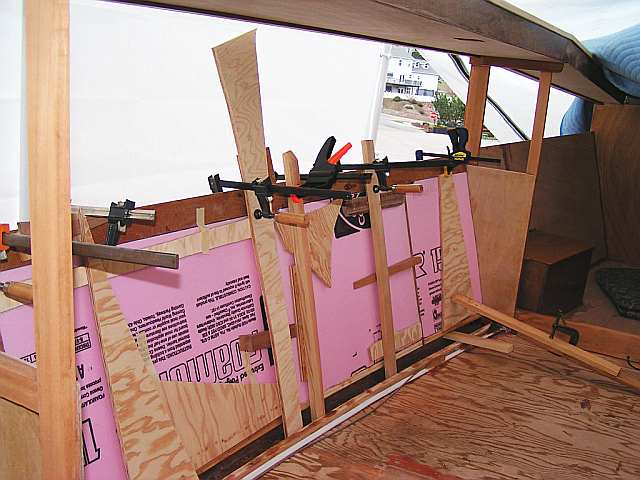
Not wanting to place temporary screws through the outside hull presented a challenge for foam installation. The faming for the gutter at the bottom of the wall helped. Pieces of wood were lodged behind the gutter frame and extended up to the coaming, where they can be clamped. As can be seen, some of those pieces were from scrap 1/2-inch plywood. Wedges are slipped between the wood pieces and the foam to apply pressure while the glue dries.
Two differet glues were tried, and both seem to be satisfactory. Epoxy with wood flour and PL300 Foamboard Adhesive were used. Epoxy, with slow hardener, gives more working time, but both are adequate. To be sure of not having excessive gaps hidden behind the wall, use abundant amounts of glue. Spread it uniformly over the area to be fastened. Voids around the foam can create water catchers during times of high humidity. Water vapor moves in, condences to a liquid, and then cannot leave. This is the reverse GoreTex effect.
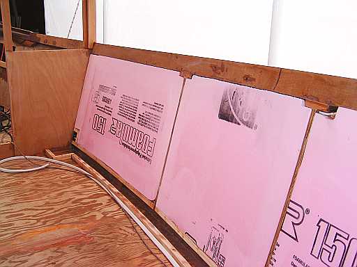
The foam has been glued to the hull in the middle compartment, ready for the inside 1/8-inch plywood. I found that it was not much extra work to make the foam sheet a good fit to the open space on the wall. This minimized the amount of pour-in foam needed at the edges. For the curved outer wall it is possible to make the foam a bit too long, so it will snap into place. By pushing on the foam, it is possible to find any areas that are not contacting the outer wall.
In this photo you can see the framing for the gutter along the bottom of the wall. Just forward of frame C (the back of this photo), I expanded the framing to form a well for a bilge pump. The well is big enough for a small pump, perhaps 500 GPH, and an automatic switch. There is a framed area in the wall that does not have foam, and can be used for wiring for the pump. All this type of wiring is inside either the wall or the floor, and can be seen in several of the photos.
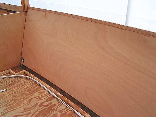
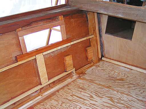
Now the 3 mm okoume plywood covers the foam. It was epoxied at all wood connections and fastened to the foam as described above. The gutter and bilge-pump well can be seen. The white wire along the gutter is the 12volt #8 cable taking power from the battery to the aft compartment. This cable stays in the floor. There is a 30A fuse in the battery compartment to insure the wire does not heat up from a short circuit.
At the top of the wall is a trim strip. The 3mm plywood wall extends above the coaming to form a drip channel along the window. It is a bit fragile without the strip. In addition, the wall is visually begging for some horizontal element along the top edge. For this purpose, the strip could be even larger.
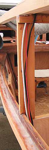
There are a few wires that run up to the ovehead. For instance, we need power from a top-mounted solar panel and red/green nav lights. These wires need a tidy path to the electrical distribution panel, that I have placed in the aft compartment. Running inside the walls and under the cabin sole does most of this, but it does not solve getting up the frame supports. I made up some wire covers to take care of this, as shown in the next photo.
These same covers can double as supports for the Lexan windows, if they are made large enough.
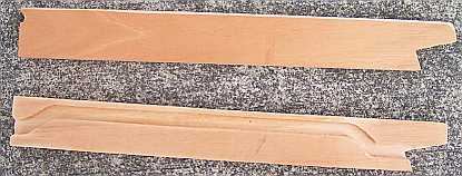
These two wire covers were fitted to the edge of the frame support. To match up with the photo above these pieces get rotated 90 degrees. Grooves about 1/2-inch wide and 3/8-inch deep were routed into the wood. The jogs in the groove move the wires away from the edge of the boat so that the same piece of wood can serve as a mounting surface for the polycarbonate windows. There is at least 1-inch of depth for the wood screws.
The next two pictures
summarize the general construction of the walls and sole.
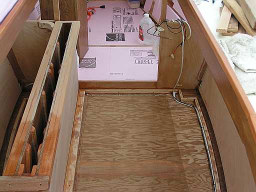
First is the center compartment, looking aft. Wood is placed at the edges of the foam to which the plywood sole is epoxied. Wiring is hidden at the edges and sealed in with more thickened epoxy. The end result is that all surfaces consist of a sandwich of plywood "bread" and foam"fixings." In this picture, a bronze screen can be seen on the bottom. This is an extra I added for use as a ground for the ham radio, and not generally needed. It ends up epoxy covered when the foam is glued into place.
Now the aft compartment, looking to the starboard side. The sole foam has been epoxied into place, with only the 6 mm plywood covering now visible. This will be covered with fibergalss before painting. The wall shows a pair of of backing blocks where the rowing foot braces attach. Also the areas around the oar ports were re-inforced to minimize flexing. More re-inforcement is seen at the top of the wall where the after-deck blends to the hull.
Back to Building Birdwatcher-2 main page
This was last revised 25 April 2007. Bob Larkin, Corvallis, Oregon